
Homework Answers


 I
hope I could help u
I
hope I could help u
Add Answer to:
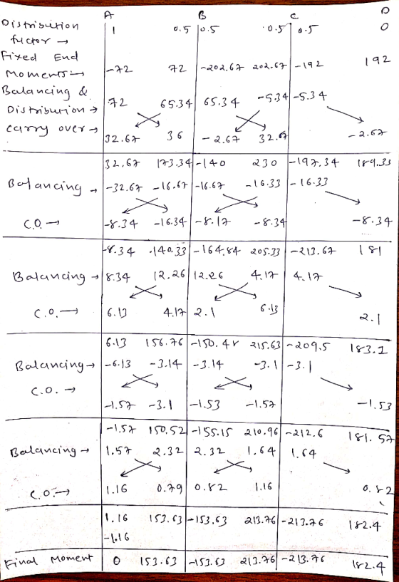
Analyse the 3 span beam shown in the Figure below by the method of moment distribution...
Moment distribution methods
Determine the reactions and draw the shear and bending moment diagrams for the shown beam using moments distribution method. 160 kN 15 kN/m 30 kN/m 3 m 6 m El-constant
Use the graphical method to construct the shear-force and bending-moment diagrams for the beam shown.
 Use the graphical method to construct the shear-force and bending-moment diagrams for the beam shown. Label all significant points on each diagram and identify the maximum moments along with their respective locations. For all answers entered, use the sign convention for shear forces and bending moments. (a) Find the location x and the corresponding bending moment M at the one point between A and B at which the shear force equals zero. (b) Consider the entire beam and determine the maximum positive...
Use the graphical method to construct the shear-force and bending-moment diagrams for the beam shown. Label...
 Use the graphical method to construct the shear-force and bending-moment diagrams for the beam shown. Label all significant points on each diagram and identify the maximum moments along with their respective locations. For all answers entered, use the sign convention for shear forces and bending moments (a) Find the location x and the corresponding bending moment M at the one point between A and D at which the shear force equals zero. (b) Consider the entire beam and determine the...
x7=12KN , x8=19kN/m, x4=4m, x5=39m, x6=5m, Q2. In the 3-span beam shown in the Figure 2, the...
 x7=12KN , x8=19kN/m, x4=4m, x5=39m, x6=5m,
Q2. In the 3-span beam shown in the Figure 2, the support at C settles by 15 mm. Using the method of moment distribution method, a) Calculate joint moments (10 marks); b) Draw the bending moment diagram (10 marks); c) Calculate the supports' vertical reactions (10 marks); and d) Draw the shear force diagram (5 marks). Hint: For the calculation of Fixed End Moments, you can use the principle of superposition to add the settlement-related...
x7=12KN , x8=19kN/m, x4=4m, x5=39m, x6=5m,
Q2. In the 3-span beam shown in the Figure 2, the support at C settles by 15 mm. Using the method of moment distribution method, a) Calculate joint moments (10 marks); b) Draw the bending moment diagram (10 marks); c) Calculate the supports' vertical reactions (10 marks); and d) Draw the shear force diagram (5 marks). Hint: For the calculation of Fixed End Moments, you can use the principle of superposition to add the settlement-related...
I need an answer for question 3 with steps please. Thank you half the load over Problem 2 eben The beam shown below...
 I need an answer for question 3 with steps please. Thank
you
half the load over Problem 2 eben The beam shown below with a uniformly span, with w3 kip/th and L 20 t shear force and bending moment diagrams for the beam using the standard sign convention Draw clear, complete and accurate Free Body Diagrams Problem 3: Siven: The beam below with a uniformly distributed load in the center span and concentrated moments at each end of the cantilever...
I need an answer for question 3 with steps please. Thank
you
half the load over Problem 2 eben The beam shown below with a uniformly span, with w3 kip/th and L 20 t shear force and bending moment diagrams for the beam using the standard sign convention Draw clear, complete and accurate Free Body Diagrams Problem 3: Siven: The beam below with a uniformly distributed load in the center span and concentrated moments at each end of the cantilever...
Use moment distribution method or slope deflection method. The frame shown if Fig. 2.1 is supporting...
 Use moment distribution method or slope deflection
method.
The frame shown if Fig. 2.1 is supporting a lateral load of 60 kN and a gravity load of 50 kNIm. Neglect the weight of the members (a) Determine th reaction forces. (b) Draw the axial, shear, and bending moment and qualitative deflected shape diagrams of the frame. Specify values at a change of loading positions and at all points of zero shear and moment. Use slope-deflection method 2m Fig. 2.1 w...
Use moment distribution method or slope deflection
method.
The frame shown if Fig. 2.1 is supporting a lateral load of 60 kN and a gravity load of 50 kNIm. Neglect the weight of the members (a) Determine th reaction forces. (b) Draw the axial, shear, and bending moment and qualitative deflected shape diagrams of the frame. Specify values at a change of loading positions and at all points of zero shear and moment. Use slope-deflection method 2m Fig. 2.1 w...
2. (70pt) For the system shown below: w bending moment (M) and shear force diagrams (V) using Moment Distribution (...
 2. (70pt) For the system shown below: w bending moment (M) and shear force diagrams (V) using Moment Distribution (Cross) or Slope Deflection Method. 90 kN/m 40 kN 41 80 kN/m 5m 21 2 2m 5m 31 5 8m 4m 4m CH y 12 31
2. (70pt) For the system shown below: w bending moment (M) and shear force diagrams (V) using Moment Distribution (Cross) or Slope Deflection Method. 90 kN/m 40 kN 41 80 kN/m 5m 21 2 2m...
2. (70pt) For the system shown below: w bending moment (M) and shear force diagrams (V) using Moment Distribution (Cross) or Slope Deflection Method. 90 kN/m 40 kN 41 80 kN/m 5m 21 2 2m 5m 31 5 8m 4m 4m CH y 12 31
2. (70pt) For the system shown below: w bending moment (M) and shear force diagrams (V) using Moment Distribution (Cross) or Slope Deflection Method. 90 kN/m 40 kN 41 80 kN/m 5m 21 2 2m...
4. For the beam and loading shown, draw the shear force and bending moment diagrams and...
 4. For the beam and loading shown, draw the shear force and bending moment diagrams and determine the maximum bending and shear force and their locations. 20 KN 40 KN B D 250 mm |--2.5 m- 3m-4-2 m 80 mm 5. For the beam and loading shown, draw the shear force and bending moment diagrams and determine the maximum bending and shear force and their locations. 50 KN
Q2b Using the direct stiffness method, determine for the beam shown: a) the displacements and rotations...
 Q2b Using the direct stiffness method, determine for the beam shown: a) the displacements and rotations of the nodes, the shear forces and moments at the nodes b) Subsequently, draw the deflected shape, shear force and bending moment diagrams. 4m rM Take: El 5 X 10⁶ Nm2, F 10 kN and w 4 kN/m.
A continuous beam ABC shown in Figure 2 is fixed at A. Supports at B and C are rollers. A uniform distributed load 40kN...
 A continuous beam ABC shown in Figure 2 is fixed at A. Supports at B and C are rollers. A uniform distributed load 40kN/m is applied force acts downward on the span of BC as shown in Figure 2. The EI of the beam is over the span of AB and a 60kN constant (a) Determine the internal moments at A and B using the slope-deflection method [10 marks] (b) Draw the bending values of bending (c) Sketch the deformed...
 Use the graphical method to construct the shear-force and bending-moment diagrams for the beam shown. Label all significant points on each diagram and identify the maximum moments along with their respective locations. For all answers entered, use the sign convention for shear forces and bending moments. (a) Find the location x and the corresponding bending moment M at the one point between A and B at which the shear force equals zero. (b) Consider the entire beam and determine the maximum positive...
 Use the graphical method to construct the shear-force and bending-moment diagrams for the beam shown. Label all significant points on each diagram and identify the maximum moments along with their respective locations. For all answers entered, use the sign convention for shear forces and bending moments (a) Find the location x and the corresponding bending moment M at the one point between A and D at which the shear force equals zero. (b) Consider the entire beam and determine the...
 x7=12KN , x8=19kN/m, x4=4m, x5=39m, x6=5m,
Q2. In the 3-span beam shown in the Figure 2, the support at C settles by 15 mm. Using the method of moment distribution method, a) Calculate joint moments (10 marks); b) Draw the bending moment diagram (10 marks); c) Calculate the supports' vertical reactions (10 marks); and d) Draw the shear force diagram (5 marks). Hint: For the calculation of Fixed End Moments, you can use the principle of superposition to add the settlement-related...
x7=12KN , x8=19kN/m, x4=4m, x5=39m, x6=5m,
Q2. In the 3-span beam shown in the Figure 2, the support at C settles by 15 mm. Using the method of moment distribution method, a) Calculate joint moments (10 marks); b) Draw the bending moment diagram (10 marks); c) Calculate the supports' vertical reactions (10 marks); and d) Draw the shear force diagram (5 marks). Hint: For the calculation of Fixed End Moments, you can use the principle of superposition to add the settlement-related...
 I need an answer for question 3 with steps please. Thank
you
half the load over Problem 2 eben The beam shown below with a uniformly span, with w3 kip/th and L 20 t shear force and bending moment diagrams for the beam using the standard sign convention Draw clear, complete and accurate Free Body Diagrams Problem 3: Siven: The beam below with a uniformly distributed load in the center span and concentrated moments at each end of the cantilever...
I need an answer for question 3 with steps please. Thank
you
half the load over Problem 2 eben The beam shown below with a uniformly span, with w3 kip/th and L 20 t shear force and bending moment diagrams for the beam using the standard sign convention Draw clear, complete and accurate Free Body Diagrams Problem 3: Siven: The beam below with a uniformly distributed load in the center span and concentrated moments at each end of the cantilever...
 Use moment distribution method or slope deflection
method.
The frame shown if Fig. 2.1 is supporting a lateral load of 60 kN and a gravity load of 50 kNIm. Neglect the weight of the members (a) Determine th reaction forces. (b) Draw the axial, shear, and bending moment and qualitative deflected shape diagrams of the frame. Specify values at a change of loading positions and at all points of zero shear and moment. Use slope-deflection method 2m Fig. 2.1 w...
Use moment distribution method or slope deflection
method.
The frame shown if Fig. 2.1 is supporting a lateral load of 60 kN and a gravity load of 50 kNIm. Neglect the weight of the members (a) Determine th reaction forces. (b) Draw the axial, shear, and bending moment and qualitative deflected shape diagrams of the frame. Specify values at a change of loading positions and at all points of zero shear and moment. Use slope-deflection method 2m Fig. 2.1 w...
 2. (70pt) For the system shown below: w bending moment (M) and shear force diagrams (V) using Moment Distribution (Cross) or Slope Deflection Method. 90 kN/m 40 kN 41 80 kN/m 5m 21 2 2m 5m 31 5 8m 4m 4m CH y 12 31
2. (70pt) For the system shown below: w bending moment (M) and shear force diagrams (V) using Moment Distribution (Cross) or Slope Deflection Method. 90 kN/m 40 kN 41 80 kN/m 5m 21 2 2m...
2. (70pt) For the system shown below: w bending moment (M) and shear force diagrams (V) using Moment Distribution (Cross) or Slope Deflection Method. 90 kN/m 40 kN 41 80 kN/m 5m 21 2 2m 5m 31 5 8m 4m 4m CH y 12 31
2. (70pt) For the system shown below: w bending moment (M) and shear force diagrams (V) using Moment Distribution (Cross) or Slope Deflection Method. 90 kN/m 40 kN 41 80 kN/m 5m 21 2 2m...
 4. For the beam and loading shown, draw the shear force and bending moment diagrams and determine the maximum bending and shear force and their locations. 20 KN 40 KN B D 250 mm |--2.5 m- 3m-4-2 m 80 mm 5. For the beam and loading shown, draw the shear force and bending moment diagrams and determine the maximum bending and shear force and their locations. 50 KN
 Q2b Using the direct stiffness method, determine for the beam shown: a) the displacements and rotations of the nodes, the shear forces and moments at the nodes b) Subsequently, draw the deflected shape, shear force and bending moment diagrams. 4m rM Take: El 5 X 10⁶ Nm2, F 10 kN and w 4 kN/m.
 A continuous beam ABC shown in Figure 2 is fixed at A. Supports at B and C are rollers. A uniform distributed load 40kN/m is applied force acts downward on the span of BC as shown in Figure 2. The EI of the beam is over the span of AB and a 60kN constant (a) Determine the internal moments at A and B using the slope-deflection method [10 marks] (b) Draw the bending values of bending (c) Sketch the deformed...
Most questions answered within 3 hours.
-
McCracken Aerial,
Inc., produces and sells a unique type of TV antenna. The company
has just...
asked 5 minutes ago -
Write a program to prompt the user for hours and rate per hour
using input to...
asked 30 minutes ago -
Hi, please help
1)Draw two molecules that could hydrogen bond with each other.
Draw and indicate...
asked 33 minutes ago -
Using Java, I created 3 files, Pizza,PizzaOrder, and
PizzaOrder_Demo that I attached down below. But I...
asked 32 minutes ago -
a. An 8-bit successive approximation ADC has a reference voltage
of 10 V. Calculate the resolution...
asked 43 minutes ago -
The distance between the two hydrogen nuclei in the H2 molecule
is 110 pm (picometer). How...
asked 44 minutes ago -
write an article about drone effect on
construction safety.
asked 48 minutes ago -
Consider the following data for a dependent variable y and two
independent variables, x1 and x2....
asked 1 hour ago -
what is the most likely shape for a distribution with a mean of
40 and a...
asked 59 minutes ago -
The work function, Φ0 (or W0), for cesium is 3.43×10⁻¹⁹ J. The
frequency of a photon...
asked 1 hour ago -
18.54----At the surface of Venus the average temperature is a
balmy 460 ∘C due to the...
asked 1 hour ago -
#1. A food has been ingested. Identify all of the anatomic
structures and substructures it travels...
asked 56 minutes ago