![(a) The impulse response hfn of an FIR filter satisfies the following property: h[n]- otherwise where M is an even integer. Derive the filters frequency response and show that it has a linear phase. Why is linear phase a desired property ? (b) You are asked to design a linear-phase FIR filter. The required pass-band is from 1,000 Hz to 3,000 Hz. The input signals sampling frequency is 16, 000Hz e the pass-band in the w domain 1. GlV n ii. Derive the ideal impulse response (which is non-causal); iii. By preserving the most significant filter coefficients, give the impulse response of a linear-phase FIR filter of order 8; iv. Plot the magnitude response of the FIR filter. (c) Use the MATLAB function firl to re-do (b). Provide the MATLAB codes and list the filter coefficients obtained](http://img.homeworklib.com/questions/b4fe1ab0-505c-11eb-9433-b9b927522c61.png?x-oss-process=image/resize,w_560)
Homework Answers
load chirp
y = y + 0.25*(rand(size(y))-0.5);
f = [0 0.48 0.48 1];
mhi = [0 0 1 1];
bhi = fir2(34,f,mhi);

freqz(bhi,1)
outhi = filter(bhi,1,y);
t = (0:length(y)-1)/Fs;

subplot(2,1,1)
plot(t,y)
title('Original Signal')
ylim([-1.2 1.2])

subplot(2,1,2)
plot(t,outhi)
title('Higpass Filtered Signal')
xlabel('Time (s)')
ylim([-1.2 1.2])
mlo = [1 1 0 0];
blo = fir2(34,f,mlo);
outlo = filter(blo,1,y);

subplot(2,1,1)
plot(t,y)
title('Original Signal')
ylim([-1.2 1.2])

subplot(2,1,2)
plot(t,outlo)
title('Lowpass Filtered Signal')
xlabel('Time (s)')
ylim([-1.2 1.2])
f = [0 0.6 0.6 1];
m = [1 1 0 0];

b1 = fir2(30,f,m);
[h1,w] = freqz(b1,1);

plot(f,m,w/pi,abs(h1))
xlabel('\omega / \pi')
lgs = {'Ideal','fir2 default'};
legend(lgs)
b2 = fir2(30,f,m,64);
h2 = freqz(b2,1);

hold on
plot(w/pi,abs(h2))
lgs{3} = 'npt = 64';
legend(lgs)
b3 = fir2(30,f,m,64,13);
h3 = freqz(b3,1);

plot(w/pi,abs(h3))
lgs{4} = 'lap = 13';
legend(lgs)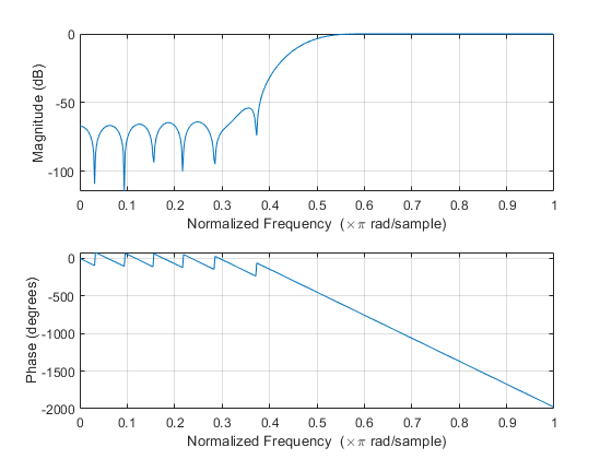


Add Answer to:
(a) The impulse response hfn of an FIR filter satisfies the following property: h[n]- otherwise where...
a) The transfer function of an ideal low-pass filter is and its impulse response is where...
 a) The transfer function of an ideal low-pass filter is and its impulse response is where oc is the cut-off frequency i) Is hLP[n] a finite impulse response (FIR) filter or an infinite impulse response filter (IIR)? Explain your answer ii Is hLP[n] a causal or a non-causal filter? Explain your answer iii) If ae-0. IT, plot the magnitude responses for the following impulse responses b) i) Let the five impulse response samples of a causal FIR filter be given...
Consider a filter characterized by the following impulse response: h [1, 2, -1, 1] Which of...
 Consider a filter characterized by the following impulse response: h [1, 2, -1, 1] Which of the following statements are true about the filter? Assume that the sampling frequency in this application is 8192 Hz. (You may use MATLAB to help you analyze this filter). o 1. The filter characterized by h = 1 2 1 1 Is a frequency selective FIR filter. In terms of the frequency response the ter is best characterized as a band-stop filter with a...
Design a high pass FIR filter to meet the following specifications. Provide all equations needed to...
Design a high pass FIR filter to meet the following specifications. Provide all equations needed to produce the filter's impulse response. Pass band: 14.66 - 22 kHz Stop band rejection: min 40 dB Pass band ripple: max. 5% Sampling frquency: 48 kHz Use either a Hamming, Hann or Kaiser window. Derive the first three filter coefficients.
DSP Lab Exercise 9 Given below are the Impulse Response h(n), of the four main types of FIR Digit...
 DSP Lab Exercise 9 Given below are the Impulse Response h(n), of the four main types of FIR Digital filters. Use appropriate MATLAB expressions to find: a) System Response (H(z) b) Pole-zero diagram c) Amplitude Response d) Phase Response 1. FIR Low-Pass Digital Filter ,n= 0.1 |[d(n) + δ(n-I))-1 h(n) 0, otherwise 2. FIR High-Pass Digital Filter 0, otherwise 3. FIR Band-Pass Digital Filter 0, otherwise 4. FIR Band-Stop Digital Filter , n = 0,2 0, otherwise Note: Your final...
The impulse response of an ideal band pass filter is given by the equation: n 0 h(n)=-sin(nw.) wl...
 The impulse response of an ideal band pass filter is given by the equation: n 0 h(n)=-sin(nw.) wl sin(nw!) nヂ0 Using the above equation, write a Matlab program that implements an approximation for the band pass filter with cut-off frequencies ω1-0.2π rad/sample and c02-0.3t rad/sample. Set the order of the filter to 100 or 101. Use a Bartlett window here. Plot the frequency and phase responses of this digital filter.
The impulse response of an ideal band pass filter is...
The impulse response of an ideal band pass filter is given by the equation: n 0 h(n)=-sin(nw.) wl sin(nw!) nヂ0 Using the above equation, write a Matlab program that implements an approximation for the band pass filter with cut-off frequencies ω1-0.2π rad/sample and c02-0.3t rad/sample. Set the order of the filter to 100 or 101. Use a Bartlett window here. Plot the frequency and phase responses of this digital filter.
The impulse response of an ideal band pass filter is...
1. The impulse response of an ideal band pass filter is given by the equation: n=0 h(n)w2 sin(n w...
 Do it using Matlab.
1. The impulse response of an ideal band pass filter is given by the equation: n=0 h(n)w2 sin(n w2) w1 sin (n w1) T nwW2 Using the above equation, write a Matlab program that implements an approximation for the band pass filter with cut-off frequencies (1-0.2π rad/sample and ω2-0.3π rad/sample. Set the order of the filter to 100 or 101. Use a Bartlett window here. Plot the frequency and phase responses of this digital filter. Hint...
Do it using Matlab.
1. The impulse response of an ideal band pass filter is given by the equation: n=0 h(n)w2 sin(n w2) w1 sin (n w1) T nwW2 Using the above equation, write a Matlab program that implements an approximation for the band pass filter with cut-off frequencies (1-0.2π rad/sample and ω2-0.3π rad/sample. Set the order of the filter to 100 or 101. Use a Bartlett window here. Plot the frequency and phase responses of this digital filter. Hint...
b) When designing a FIR filters, the impulse response of the ideal low-pass filter is usually modified by multiplying i...
 b) When designing a FIR filters, the impulse response of the ideal low-pass filter is usually modified by multiplying it by a windowing function such as the Hamming window which is defined, for an odd number N of samples, by: (2n)-(N-I)-ns(N-1) N-12 wlnl 0.54 + 0.46 cos i What are the advantages of windowing with this function compared 2 with a standard rectangular window? ii) Design a 10th Order Hamming windowed FIR low-pass filter with cut- off frequency at 1000...
Q8) Consider the following causal linear time-invariant (LTI) discrete-time filter with input x[n...
 Q8) Consider the following causal linear time-invariant (LTI) discrete-time filter with input x[n] and output y[n] described by bx[n-21- ax[n-3 for n 2 0, where a and b are real-valued positive coefficients. A) Is this a finite impulse response (FIR) or infinite impulse response (IIR) filter? Why? B) What are the initial conditions and their values? Why? C) Draw the block diagram of the filter relating input x[n] and output y[n] D) Derive a formula for the transfer function in...
Question 4 (a) Find the DFT of the series x[n)-(0.2,1,1,0.2), and sketch the magnitude of the resulting spectral components [10 marks] (b) For a discrete impulse response, h[n], that is symmetric...
 Question 4 (a) Find the DFT of the series x[n)-(0.2,1,1,0.2), and sketch the magnitude of the resulting spectral components [10 marks] (b) For a discrete impulse response, h[n], that is symmetric about the origin, the spectral coefficients of the signal, H(k), can be obtained by use of the DFT He- H(k)- H-(N-1)/2 Conversely, if the spectral coefficients, H(k), are known (and are even and symmetrical about k-0), the original signal, h[n], can be reconstituted using the inverse DFT 1 (N-D/2...
Determine the coefficients b0, b1, b2, of a generalized linear-phase FIR filter 1. (GLP FIR Filters]...
 Determine the coefficients b0,
b1, b2, of a generalized linear-phase FIR filter
1. (GLP FIR Filters] Determine the coefficients bo, bi, b2, of a generalized linear-phase FIR filter | d[n] = box[n] + b n - 1]+b22[n – 2] such that (i) it rejects any frequency component at wo = /3; and (ii) its frequency response is normalized so that Ha(0) = 1. Compute and sketch the magnitude and phase response of the filter to check that it satisfies the...
Determine the coefficients b0,
b1, b2, of a generalized linear-phase FIR filter
1. (GLP FIR Filters] Determine the coefficients bo, bi, b2, of a generalized linear-phase FIR filter | d[n] = box[n] + b n - 1]+b22[n – 2] such that (i) it rejects any frequency component at wo = /3; and (ii) its frequency response is normalized so that Ha(0) = 1. Compute and sketch the magnitude and phase response of the filter to check that it satisfies the...
 a) The transfer function of an ideal low-pass filter is and its impulse response is where oc is the cut-off frequency i) Is hLP[n] a finite impulse response (FIR) filter or an infinite impulse response filter (IIR)? Explain your answer ii Is hLP[n] a causal or a non-causal filter? Explain your answer iii) If ae-0. IT, plot the magnitude responses for the following impulse responses b) i) Let the five impulse response samples of a causal FIR filter be given...
 Consider a filter characterized by the following impulse response: h [1, 2, -1, 1] Which of the following statements are true about the filter? Assume that the sampling frequency in this application is 8192 Hz. (You may use MATLAB to help you analyze this filter). o 1. The filter characterized by h = 1 2 1 1 Is a frequency selective FIR filter. In terms of the frequency response the ter is best characterized as a band-stop filter with a...
 DSP Lab Exercise 9 Given below are the Impulse Response h(n), of the four main types of FIR Digital filters. Use appropriate MATLAB expressions to find: a) System Response (H(z) b) Pole-zero diagram c) Amplitude Response d) Phase Response 1. FIR Low-Pass Digital Filter ,n= 0.1 |[d(n) + δ(n-I))-1 h(n) 0, otherwise 2. FIR High-Pass Digital Filter 0, otherwise 3. FIR Band-Pass Digital Filter 0, otherwise 4. FIR Band-Stop Digital Filter , n = 0,2 0, otherwise Note: Your final...
 The impulse response of an ideal band pass filter is given by the equation: n 0 h(n)=-sin(nw.) wl sin(nw!) nヂ0 Using the above equation, write a Matlab program that implements an approximation for the band pass filter with cut-off frequencies ω1-0.2π rad/sample and c02-0.3t rad/sample. Set the order of the filter to 100 or 101. Use a Bartlett window here. Plot the frequency and phase responses of this digital filter.
The impulse response of an ideal band pass filter is...
The impulse response of an ideal band pass filter is given by the equation: n 0 h(n)=-sin(nw.) wl sin(nw!) nヂ0 Using the above equation, write a Matlab program that implements an approximation for the band pass filter with cut-off frequencies ω1-0.2π rad/sample and c02-0.3t rad/sample. Set the order of the filter to 100 or 101. Use a Bartlett window here. Plot the frequency and phase responses of this digital filter.
The impulse response of an ideal band pass filter is...
 Do it using Matlab.
1. The impulse response of an ideal band pass filter is given by the equation: n=0 h(n)w2 sin(n w2) w1 sin (n w1) T nwW2 Using the above equation, write a Matlab program that implements an approximation for the band pass filter with cut-off frequencies (1-0.2π rad/sample and ω2-0.3π rad/sample. Set the order of the filter to 100 or 101. Use a Bartlett window here. Plot the frequency and phase responses of this digital filter. Hint...
Do it using Matlab.
1. The impulse response of an ideal band pass filter is given by the equation: n=0 h(n)w2 sin(n w2) w1 sin (n w1) T nwW2 Using the above equation, write a Matlab program that implements an approximation for the band pass filter with cut-off frequencies (1-0.2π rad/sample and ω2-0.3π rad/sample. Set the order of the filter to 100 or 101. Use a Bartlett window here. Plot the frequency and phase responses of this digital filter. Hint...
 b) When designing a FIR filters, the impulse response of the ideal low-pass filter is usually modified by multiplying it by a windowing function such as the Hamming window which is defined, for an odd number N of samples, by: (2n)-(N-I)-ns(N-1) N-12 wlnl 0.54 + 0.46 cos i What are the advantages of windowing with this function compared 2 with a standard rectangular window? ii) Design a 10th Order Hamming windowed FIR low-pass filter with cut- off frequency at 1000...
 Q8) Consider the following causal linear time-invariant (LTI) discrete-time filter with input x[n] and output y[n] described by bx[n-21- ax[n-3 for n 2 0, where a and b are real-valued positive coefficients. A) Is this a finite impulse response (FIR) or infinite impulse response (IIR) filter? Why? B) What are the initial conditions and their values? Why? C) Draw the block diagram of the filter relating input x[n] and output y[n] D) Derive a formula for the transfer function in...
 Question 4 (a) Find the DFT of the series x[n)-(0.2,1,1,0.2), and sketch the magnitude of the resulting spectral components [10 marks] (b) For a discrete impulse response, h[n], that is symmetric about the origin, the spectral coefficients of the signal, H(k), can be obtained by use of the DFT He- H(k)- H-(N-1)/2 Conversely, if the spectral coefficients, H(k), are known (and are even and symmetrical about k-0), the original signal, h[n], can be reconstituted using the inverse DFT 1 (N-D/2...
 Determine the coefficients b0,
b1, b2, of a generalized linear-phase FIR filter
1. (GLP FIR Filters] Determine the coefficients bo, bi, b2, of a generalized linear-phase FIR filter | d[n] = box[n] + b n - 1]+b22[n – 2] such that (i) it rejects any frequency component at wo = /3; and (ii) its frequency response is normalized so that Ha(0) = 1. Compute and sketch the magnitude and phase response of the filter to check that it satisfies the...
Determine the coefficients b0,
b1, b2, of a generalized linear-phase FIR filter
1. (GLP FIR Filters] Determine the coefficients bo, bi, b2, of a generalized linear-phase FIR filter | d[n] = box[n] + b n - 1]+b22[n – 2] such that (i) it rejects any frequency component at wo = /3; and (ii) its frequency response is normalized so that Ha(0) = 1. Compute and sketch the magnitude and phase response of the filter to check that it satisfies the...
Most questions answered within 3 hours.
-
Based on historical data, your team knows what proportion of the
company's orders come from Males...
asked 1 minute ago -
8. Which of the following atoms has the largest magnitude
electron affinity?
(a) Sodium (Na)
(b)...
asked 3 minutes ago -
Assess the two types of tests of cognitive abilities. (
regarding HR course)
asked 8 minutes ago -
1.Write an inspiring vision statement for an organization where
you work or have worked. If the...
asked 10 minutes ago -
2. Is fair trade coffee sustainable for the mass market,
or is it a niche product...
asked 10 minutes ago -
Please answer this asap in MATLAB.
In the following for loop, the the loop is executed...
asked 23 minutes ago -
A 50.0-g golf ball is driven from the tee with an initial speed
of 44.6 m/s...
asked 17 minutes ago -
Use the molar concentration of the 50 mL solution to calculate
the moles of Cr(III) in...
asked 20 minutes ago -
Calculate the molarity of Fe3+ in solution A.
Solution A: 10 mL of 0.0600 M Fe(No3)3 ...
asked 29 minutes ago -
two dogs pull 2 strings horizontally which are tied to a sleigh.
the angle between the...
asked 29 minutes ago -
please write a paper about any ethical violation based on the
case study Stanford's Prison Experiment....
asked 50 minutes ago -
What is the advantage of considering each of the
following in calculating the work done by...
asked 57 minutes ago