

Homework Answers

![at dode vt Şc vt + vt-vizo v* [$ct toco] - va (se C00+] - Vi = vt (1000 $C+1) (Vi = 0.5 Vo [1000 $C+1]] at clode vis vlico sc](http://img.homeworklib.com/questions/02745b60-52e0-11eb-9df4-4153ab98cafd.png?x-oss-process=image/resize,w_560)
Add Answer to:
29. The Figure 16 shown below represents a 2UF Vino Lika Vour 21F W 10k 10kn...
Consider the input signal x(t) with Fourier transformation X(w) as shown in the figure below where...
 Consider the input signal x(t) with Fourier transformation X(w) as shown in the figure below where WM = 100 rad/s. The sampling frequency ws = 200 rad/s. The filter H(w) has a cut- off frequency we = 100 rad/s a) [10 points) Plot the signal P(0) b) [15 points] Plot the signal Xplo) c) [10 points] Plot the output signal X-(0) pt) - 281t - nT) x(t) H(jw) X Hij M You need to show all the steps that lead...
The circuit shown in Figure Q4-1 includes an audio source and the equivalent circuit of a...
 The circuit shown in Figure Q4-1 includes an audio source and the equivalent circuit of a loudspeaker that you have been asked to analyse. 4. a) Assuming the speaker is to operate at a single frequency of 200 Hz and is5 driven by a cosinusoidal signal with peak amplitude of 20 V; determine the equivalent impedance of the speaker When connected to the audio source, calculate the current flow i() When testing the loudspeaker detailed in Q4a) i), you can...
Q.2 (a) Given a series RL circuit as shown in Figure Q.2(a). 1092 vit) 20mF V.(t)...
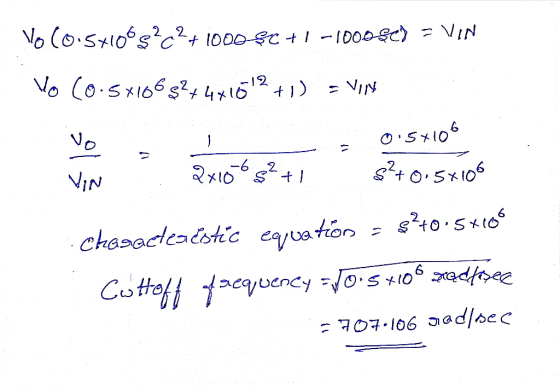
 Q.2 (a) Given a series RL circuit as shown in Figure Q.2(a). 1092 vit) 20mF V.(t) Figure 2.2(a) (i) V.(s) Determine the transfer function, Vi(s) (4 marks) Sketch the magnitude and phase Bode plots for the above transfer function. (4 marks) (iii) Determine the filter type. (2 marks) (b) For a low pass filter application, following signal is channeled through a Butterworth filter; x(t) = 2 sin ( 10Tt - (10nt -) + 3cos (50nt -) + Ssin (100nt +...
Chapter 16, Problem 16.049 (Circuit Solution) Incorrect Find the frequency-domain voltage Vo shown in the figure...
 Chapter 16, Problem 16.049 (Circuit Solution) Incorrect Find the frequency-domain voltage Vo shown in the figure below 15Ω 15Ω 5/30° A (a) Find the real part of the voltage. (b) Find the imaginary part of the voltage. (a) TT45.67 (b) T-18.12
An AC generator provides power for the circuit shown below. The generator voltage is described by...
An AC generator provides power for the circuit shown below. The generator voltage is described by E(t)=Emaxsin(ωt)E(t)=Emaxsin(ωt) where E=E= 120 V. Here, L=L= 640 mH, C=C= 160 μμF, R=R= 90 ΩΩ, and ω=ω= 40 rad/sec. 1) What is the phase angle between the generator and the current? ϕ=ϕ= -55 degrees ϕ=ϕ= 1.1 degrees ϕ=ϕ= 64 degrees ϕ=ϕ= -16 degrees ϕ=ϕ= -0.99 degrees Your submissions: A Submitted: Wednesday, July 29 at 1:02 PM Feedback: Feedback will be available after 11:59 PM...
16 Question Two charges are arranged as shown in the figure below. Calculate the electric potential...
 16 Question Two charges are arranged as shown in the figure below. Calculate the electric potential at point P. 100mm 17 Question If an electron is released from rest at point P. (see figure in question above), calculate its' velocity when it is infinitely far away from P. 18 Question For the system of capacitors shown below, there is a potential difference of 24V. 2pF 2 pF 24V (a) What is the equivalent capacitance of this system? Simplify the circuit...
PLEASE ANSWER ALL OF THE FOLLOWING QUESTIONS ASAP!' 29) In the circuit shown below, answer the...
 PLEASE ANSWER ALL OF THE FOLLOWING QUESTIONS ASAP!'
29) In the circuit shown below, answer the following questions R1 R3 w 42 12 B 28 V 232 R2 7V B2 a) Write the equations EQUATIONS 7) Given a timing circuit, you are asked to connect the following components in series. A 6-microfarad capacitor, and a 2002. They car connected with a 30 V voltage source that has angular frequency of 250 rad/s. a) What is the impedance of the entire...
PLEASE ANSWER ALL OF THE FOLLOWING QUESTIONS ASAP!'
29) In the circuit shown below, answer the following questions R1 R3 w 42 12 B 28 V 232 R2 7V B2 a) Write the equations EQUATIONS 7) Given a timing circuit, you are asked to connect the following components in series. A 6-microfarad capacitor, and a 2002. They car connected with a 30 V voltage source that has angular frequency of 250 rad/s. a) What is the impedance of the entire...
29. A section of the periodic table with all identification features removed is shown below. X...
 29. A section of the periodic table with all identification features removed is shown below. X Y Z Which element has the smallest atomic radius? A. W В. Y С. Х D. V 30. Which of the following elements would be expected to have chemical and physical properties most similar to those of the krypton (Kr)? A. Neon (Ne) B. Gallium (Ga) C. Sodium (Na) D. Tin (Sn) art II (10 points in total) ou must show all the work...
PROBLEM #2 The drawing shown below on this page (Figure 16) is a cross section through...
 PROBLEM #2 The drawing shown below on this page (Figure 16) is a cross section through the entrance of a concrete-lined irrigation canal at a low di. version dan. The reservoir water surface is maintained at 6.0 feet above the canal invert. REQUIRED: (a) If the canal invert slope is 0.0003 ft/ft, what is the maximum discharge through the canal? (b) As the canal invert slope is increased, at what slope will no further increase in the discharge occur? (e)...
A common source amplifier circuit based on a single n-channel MOSFET is shown in Figure 4b. Assume that the transconductance gm-60 mS (equivalent to mA/ V) and drain source resistance, os,...
 A common source amplifier circuit based on a single n-channel MOSFET is shown in Figure 4b. Assume that the transconductance gm-60 mS (equivalent to mA/ V) and drain source resistance, os, is so large it may be neglected. 0) Calculate the open circuit voltage gain Av Yout/ Vis. i) The amplifier has a load of 10 k2. Determine the current gain Va. = 12 V 150k 4k3 Vout Vin 200k GND = 0 V Figure 4b a) State the name...
 Consider the input signal x(t) with Fourier transformation X(w) as shown in the figure below where WM = 100 rad/s. The sampling frequency ws = 200 rad/s. The filter H(w) has a cut- off frequency we = 100 rad/s a) [10 points) Plot the signal P(0) b) [15 points] Plot the signal Xplo) c) [10 points] Plot the output signal X-(0) pt) - 281t - nT) x(t) H(jw) X Hij M You need to show all the steps that lead...
 The circuit shown in Figure Q4-1 includes an audio source and the equivalent circuit of a loudspeaker that you have been asked to analyse. 4. a) Assuming the speaker is to operate at a single frequency of 200 Hz and is5 driven by a cosinusoidal signal with peak amplitude of 20 V; determine the equivalent impedance of the speaker When connected to the audio source, calculate the current flow i() When testing the loudspeaker detailed in Q4a) i), you can...
 Q.2 (a) Given a series RL circuit as shown in Figure Q.2(a). 1092 vit) 20mF V.(t) Figure 2.2(a) (i) V.(s) Determine the transfer function, Vi(s) (4 marks) Sketch the magnitude and phase Bode plots for the above transfer function. (4 marks) (iii) Determine the filter type. (2 marks) (b) For a low pass filter application, following signal is channeled through a Butterworth filter; x(t) = 2 sin ( 10Tt - (10nt -) + 3cos (50nt -) + Ssin (100nt +...
 Chapter 16, Problem 16.049 (Circuit Solution) Incorrect Find the frequency-domain voltage Vo shown in the figure below 15Ω 15Ω 5/30° A (a) Find the real part of the voltage. (b) Find the imaginary part of the voltage. (a) TT45.67 (b) T-18.12
 16 Question Two charges are arranged as shown in the figure below. Calculate the electric potential at point P. 100mm 17 Question If an electron is released from rest at point P. (see figure in question above), calculate its' velocity when it is infinitely far away from P. 18 Question For the system of capacitors shown below, there is a potential difference of 24V. 2pF 2 pF 24V (a) What is the equivalent capacitance of this system? Simplify the circuit...
 PLEASE ANSWER ALL OF THE FOLLOWING QUESTIONS ASAP!'
29) In the circuit shown below, answer the following questions R1 R3 w 42 12 B 28 V 232 R2 7V B2 a) Write the equations EQUATIONS 7) Given a timing circuit, you are asked to connect the following components in series. A 6-microfarad capacitor, and a 2002. They car connected with a 30 V voltage source that has angular frequency of 250 rad/s. a) What is the impedance of the entire...
PLEASE ANSWER ALL OF THE FOLLOWING QUESTIONS ASAP!'
29) In the circuit shown below, answer the following questions R1 R3 w 42 12 B 28 V 232 R2 7V B2 a) Write the equations EQUATIONS 7) Given a timing circuit, you are asked to connect the following components in series. A 6-microfarad capacitor, and a 2002. They car connected with a 30 V voltage source that has angular frequency of 250 rad/s. a) What is the impedance of the entire...
 29. A section of the periodic table with all identification features removed is shown below. X Y Z Which element has the smallest atomic radius? A. W В. Y С. Х D. V 30. Which of the following elements would be expected to have chemical and physical properties most similar to those of the krypton (Kr)? A. Neon (Ne) B. Gallium (Ga) C. Sodium (Na) D. Tin (Sn) art II (10 points in total) ou must show all the work...
 PROBLEM #2 The drawing shown below on this page (Figure 16) is a cross section through the entrance of a concrete-lined irrigation canal at a low di. version dan. The reservoir water surface is maintained at 6.0 feet above the canal invert. REQUIRED: (a) If the canal invert slope is 0.0003 ft/ft, what is the maximum discharge through the canal? (b) As the canal invert slope is increased, at what slope will no further increase in the discharge occur? (e)...
 A common source amplifier circuit based on a single n-channel MOSFET is shown in Figure 4b. Assume that the transconductance gm-60 mS (equivalent to mA/ V) and drain source resistance, os, is so large it may be neglected. 0) Calculate the open circuit voltage gain Av Yout/ Vis. i) The amplifier has a load of 10 k2. Determine the current gain Va. = 12 V 150k 4k3 Vout Vin 200k GND = 0 V Figure 4b a) State the name...
Most questions answered within 3 hours.
-
Minitab Problem: Take the Lake Hume June rainfall data and find
use the processes outlined in...
asked 41 minutes ago -
X Company is trying to decide whether to continue using old
equipment to make Product A...
asked 42 minutes ago -
IN PYTHON ONLY !! Program 2: Re-work
program #5 (WeeklyHours) from the previous assignment such that...
asked 1 hour ago -
The average length of time between arrivals at a turnpike
toll-booth is 26 seconds. What is...
asked 2 hours ago -
(a) A piston at 6.1 atm contains a gas that occupies a volume of
3.5 L....
asked 4 hours ago -
Please answer true or false. Words
cannot be changed or added in to make it true...
asked 4 hours ago -
An empty test tube weighs 15.923 grams. Then,
MgCl2•6H2O is added into the test tube. After...
asked 4 hours ago -
Assume memory access is 10 units of time and disk access is
10000 units of time....
asked 4 hours ago -
1. Are all good samples random?
2. Magazines often report surveys giving statistics such as “63%...
asked 4 hours ago -
Under all the various types of market structures, firms
must eventually earn some economic profits for...
asked 4 hours ago -
Consider the following fitness regime for a single locus trait
with two co-dominant alleles: w11 =...
asked 4 hours ago -
A large cable company reports the following.
80% of its customers subscribe to its cable TV...
asked 4 hours ago