![Q. 2. (a) Using full adders and some other gates, design subtractor that subtracts an 8-bit binary number (Y.... Yo] from 8-b](http://img.homeworklib.com/questions/21188ca0-52fa-11eb-b1d8-8f0af9aa8cee.png?x-oss-process=image/resize,w_560)
Homework Answers


As HOMEWORKLIB RULES rule I have given the answer..
If you are satisfied with my answer please give me a like..
Thank you
Keep learning!!
Add Answer to:
Q. 2. (a) Using full adders and some other gates, design subtractor that subtracts an 8-bit...
4. Design a 4-bit Adder / Subtractor. Follow the steps given below. (a) Write the VHDL...
 4. Design a 4-bit Adder / Subtractor. Follow the steps given below. (a) Write the VHDL code for a 1-bit Full Adder. The VHDL code must include an entity and an architecture. (b) Draw the circuit diagram for a 4-bit Adder / Subtractor. The circuit diagram may include the following logic elements: 1-bit Full Adders (shown as a block with inputs and outputs) Any 2-input logic gates Multiplexers Do not draw the logic circuit for the 1-bit Full Adder.
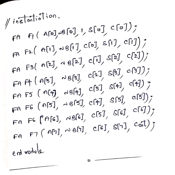
Design an 8-bit full adder using Verilog (Use only 1-bit full adders). Write the design code,...
Design an 8-bit full adder using Verilog (Use only 1-bit full adders). Write the design code, test-bench code of it, and test your design with six inputs. Note: Only use Verilog to design 8-bit full adder.
Design a full subtractor and implement it with compound static CMOS gates. The number of gates in...
 Design a full subtractor and implement it with compound static CMOS gates. The number of gates in your design should be minimized. (a) Sketch a transistor-level schematic for each gate (b) Sketch a stick diagram of the barrow output circuit. 2.
Design a full subtractor and implement it with compound static CMOS gates. The number of gates in your design should be minimized. (a) Sketch a transistor-level schematic for each gate (b) Sketch a stick diagram of the barrow output...
Design a full subtractor and implement it with compound static CMOS gates. The number of gates in your design should be minimized. (a) Sketch a transistor-level schematic for each gate (b) Sketch a stick diagram of the barrow output circuit. 2.
Design a full subtractor and implement it with compound static CMOS gates. The number of gates in your design should be minimized. (a) Sketch a transistor-level schematic for each gate (b) Sketch a stick diagram of the barrow output...
3. Design a one bit subtractor. The circuit subtracts the number Y from X and generates...
 3. Design a one bit subtractor. The circuit subtracts the number Y from X and generates a difference D bit and a borrow out Bo bit. The circuit has three inputs: X, Y and borrow in bit Bi shown in the figure below: во ID a. Derive the truth table for the function D(X,Y,Bi) and Bo(X,Y,Bi) b. Write the functions D and Bo as a canonical SOP form, using the little m notation. c. To implement the functions D and...
8/8pts Question 1 Using block diagram of 1-bit full adders create a 3-bit parallel adder (show...
 8/8pts Question 1 Using block diagram of 1-bit full adders create a 3-bit parallel adder (show all the connections between the adders and proper outputs Logic Q1jpg 4/9 pts Question 2 Consider your design, if the inputs to be added were 100, and 111, what will be the resulting sum output (Express the resulting sum in binary and base 8 using the least number of bits)? What will be the carry output (Express it only in binary using the least...
Using building blocks such as binary adders, comparators, multiplexers, decoders, encoders, and arbiters as well as logic gates, design an 8x2 popularity circuit – a circuit that accepts eight two-bit...
Using building blocks such as binary adders, comparators, multiplexers, decoders, encoders, and arbiters as well as logic gates, design an 8x2 popularity circuit – a circuit that accepts eight two-bit numbers and outputs the number of times each of the four numbers appears on the input.
Use as few 3-input NOR gates as possible to design a bubble detector circuit for 8-bit thermomete...
Use as few 3-input NOR gates as possible to design a bubble detector circuit for 8-bit thermometer code. An n-bit thermometer code represents an integer m, with m 1s followed by (n-m) 0s. 1-bit bubble is an error in coding when a solitary 0 (or 1) is found in between two 1s (or 0s). What is the size of your circuit in terms of the number of NOR gates used? Give a gate level schematic diagram for your circuit. Implement...
1. Using only half adders, design a four-bit incrementer circuit (a circuit that adds 1 to...
 1. Using only half adders, design a four-bit incrementer circuit (a circuit that adds 1 to a four- bit binary number). 2. Using only 2-to-4 line decoders with enable, construct a 4-to-16 line decoder. 3. Using a decoder and external gates, design the combinational circuit defined by the following three Boolean functions: F = x'y'z' + x2 F2 = xy'z' + x'y F3 = x'y'z + xy
Design a combinational circuit that adds 1 to 3-bit unsigned binary number and produces an unsigned...
 Design a combinational circuit that adds 1 to 3-bit unsigned binary number and produces an unsigned binary result. Do the following: (1) determine the number of inputs/outputs, (2) write the truth table, (3) simplify the output functions by using maps and (4) draw the logic diagram by using AND OR and NOT gates. Show the truth table, the map, and the logic diagram. Do NOT use adders.
Tim Question 1 Atte 20 pts 2H 24 Design a 1-bit Full Adder using NOR gates...
 Tim Question 1 Atte 20 pts 2H 24 Design a 1-bit Full Adder using NOR gates only, you must include and show: Truth tables, detail logic gate circuit designs, and Boolean expressions Upload Choose a File 20 pts Question 2 Design a 4-bit Full Adder with inputs (Xo...X3, Yo...Y3) in which inputs X are connect to two 4-bit registers via four 2-to-1 Multiplexers and inputs Y are connected to two other 4-bit registers via four 2-to-1 Multiplexers. In this case...
 4. Design a 4-bit Adder / Subtractor. Follow the steps given below. (a) Write the VHDL code for a 1-bit Full Adder. The VHDL code must include an entity and an architecture. (b) Draw the circuit diagram for a 4-bit Adder / Subtractor. The circuit diagram may include the following logic elements: 1-bit Full Adders (shown as a block with inputs and outputs) Any 2-input logic gates Multiplexers Do not draw the logic circuit for the 1-bit Full Adder.
 Design a full subtractor and implement it with compound static CMOS gates. The number of gates in your design should be minimized. (a) Sketch a transistor-level schematic for each gate (b) Sketch a stick diagram of the barrow output circuit. 2.
Design a full subtractor and implement it with compound static CMOS gates. The number of gates in your design should be minimized. (a) Sketch a transistor-level schematic for each gate (b) Sketch a stick diagram of the barrow output...
Design a full subtractor and implement it with compound static CMOS gates. The number of gates in your design should be minimized. (a) Sketch a transistor-level schematic for each gate (b) Sketch a stick diagram of the barrow output circuit. 2.
Design a full subtractor and implement it with compound static CMOS gates. The number of gates in your design should be minimized. (a) Sketch a transistor-level schematic for each gate (b) Sketch a stick diagram of the barrow output...
 3. Design a one bit subtractor. The circuit subtracts the number Y from X and generates a difference D bit and a borrow out Bo bit. The circuit has three inputs: X, Y and borrow in bit Bi shown in the figure below: во ID a. Derive the truth table for the function D(X,Y,Bi) and Bo(X,Y,Bi) b. Write the functions D and Bo as a canonical SOP form, using the little m notation. c. To implement the functions D and...
 8/8pts Question 1 Using block diagram of 1-bit full adders create a 3-bit parallel adder (show all the connections between the adders and proper outputs Logic Q1jpg 4/9 pts Question 2 Consider your design, if the inputs to be added were 100, and 111, what will be the resulting sum output (Express the resulting sum in binary and base 8 using the least number of bits)? What will be the carry output (Express it only in binary using the least...
 1. Using only half adders, design a four-bit incrementer circuit (a circuit that adds 1 to a four- bit binary number). 2. Using only 2-to-4 line decoders with enable, construct a 4-to-16 line decoder. 3. Using a decoder and external gates, design the combinational circuit defined by the following three Boolean functions: F = x'y'z' + x2 F2 = xy'z' + x'y F3 = x'y'z + xy
 Design a combinational circuit that adds 1 to 3-bit unsigned binary number and produces an unsigned binary result. Do the following: (1) determine the number of inputs/outputs, (2) write the truth table, (3) simplify the output functions by using maps and (4) draw the logic diagram by using AND OR and NOT gates. Show the truth table, the map, and the logic diagram. Do NOT use adders.
 Tim Question 1 Atte 20 pts 2H 24 Design a 1-bit Full Adder using NOR gates only, you must include and show: Truth tables, detail logic gate circuit designs, and Boolean expressions Upload Choose a File 20 pts Question 2 Design a 4-bit Full Adder with inputs (Xo...X3, Yo...Y3) in which inputs X are connect to two 4-bit registers via four 2-to-1 Multiplexers and inputs Y are connected to two other 4-bit registers via four 2-to-1 Multiplexers. In this case...
Most questions answered within 3 hours.
-
2) You are given the task of finding a representation for a
circle in a drawing...
asked 48 minutes ago -
STUDY QUESTION: Does use of diet drug fen-phen
(fenfluramine-phentermine) cause valvular heart disease?
HINT: Valvular heart...
asked 40 minutes ago -
1. An object weighing 40 N rests on a surface. The coefficient
of friction is 0.35....
asked 1 hour ago -
Investor company owns 35% of investee company voting stock and
accounts for the investment under the...
asked 3 hours ago -
The number of major faults on a randomly chosen 1 km stretch of
highway has a...
asked 3 hours ago -
Consider the competitive environment of Starbuck's, Progressive
Insurance, a manufacturing firm with low turnover, or a...
asked 4 hours ago -
3. Gains from trade
Consider two neighbouring island countries called Euphoria and
Contente. They each have...
asked 6 hours ago -
A business executive has the option to invest money in two
plans: Plan A guarantees that...
asked 8 hours ago -
Hello, can someone please help me answer this question?
How much heat is absorbed by a...
asked 8 hours ago -
. A marketing researcher conducted a survey of 25 shoppers
randomly selected at the local mall...
asked 8 hours ago -
Create an comprehensive response to the
following:
Antimicrobial agents work on a multitude of microbes (bacteria,...
asked 8 hours ago -
6.13 LAB: Step counter. Section 6.3.
A pedometer treats walking 2,000 steps as walking 1 mile....
asked 8 hours ago