

Homework Answers


Add Answer to:
Problem8 The voltage source V-25V. Determine: 10Ω 15Ω 30Ω 20Ω 40Ω SPECIFY EXPLICITLY WHAT METHOD YOU...
Determine the voltage across resistor R2=40ΩR2=40Ω in the circuit shown in (Figure 1), where vs=60Vvs=60V, R1=20ΩR1=20Ω,...
 Determine the voltage across resistor R2=40ΩR2=40Ω in the
circuit shown in (Figure 1), where vs=60Vvs=60V, R1=20ΩR1=20Ω,
R3=30ΩR3=30Ω, and R4=40Ω
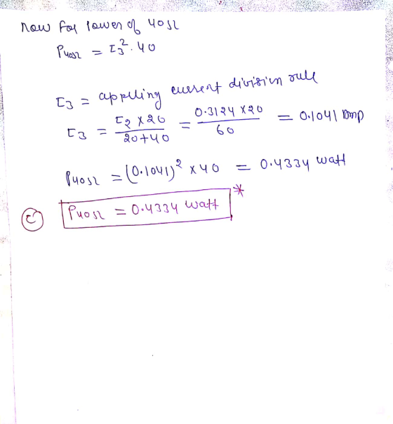
Question 6 Part A Determine the voltage across resistor R2 = 40 2 in the circuit shown in (Figure 1), where us = 60 V, R1 = 20 12 R3 = 30 12, and R4 = 40 12 Express your answer in volts to three significant figures. View Available Hint(s) Learning Goal: To determine the voltage, current, and power of circuit...
Determine the voltage across resistor R2=40ΩR2=40Ω in the
circuit shown in (Figure 1), where vs=60Vvs=60V, R1=20ΩR1=20Ω,
R3=30ΩR3=30Ω, and R4=40Ω
Question 6 Part A Determine the voltage across resistor R2 = 40 2 in the circuit shown in (Figure 1), where us = 60 V, R1 = 20 12 R3 = 30 12, and R4 = 40 12 Express your answer in volts to three significant figures. View Available Hint(s) Learning Goal: To determine the voltage, current, and power of circuit...
8. A simple circuit is composed of an ideal 100 v battery in series with three resistors (R1 = 10Ω, R2 = 20Ω, R3 = 30Ω). Which of the following statements is true? Statement A: Each resistor carries t...
 8. A simple circuit is composed of an ideal 100 v battery
in series with three resistors (R1 = 10Ω, R2 = 20Ω, R3 = 30Ω).
Which of the following statements is true?
Statement A: Each resistor carries the same current.
Statement B: Each resistor has the same voltage.
Statement C: Each resistor dissipates the same amount energy per
second.
Statement D: The battery power output is greater than the power
output of Resistor 1.
a. Only A is true....
8. A simple circuit is composed of an ideal 100 v battery
in series with three resistors (R1 = 10Ω, R2 = 20Ω, R3 = 30Ω).
Which of the following statements is true?
Statement A: Each resistor carries the same current.
Statement B: Each resistor has the same voltage.
Statement C: Each resistor dissipates the same amount energy per
second.
Statement D: The battery power output is greater than the power
output of Resistor 1.
a. Only A is true....
Q4/// What is the current of the 40 v ?voltage source of the circuit below SA...
 Q4/// What is the current of the 40 v ?voltage source of the circuit below SA 202 w 802 w 103 40 20 V 40 V Current source Voltage source leave question o 13 A 0.5 A O 12A O 10 A 1A O أخرى: Q5/// The maximum power dissipated in a 4 load is 100 w when connected to a d.c. voltage V and internal resistance R. Calculate: the current in the load, internal *.resistance R, and voltage V...
In Problems 4.1 to 4.6, the input voltage V, is dc and positive with Switch 4...
 In Problems 4.1 to 4.6, the input voltage V, is dc and positive with Switch 4 the polarity shown. Specify how to implement the switches using a position minimal number of diodes and transistors, such that the converter operates over the entire range of duty cycles OSDS 1. The switch states should vary as shown in Fig. 4.56. You may assume that the inductor current ripples and capacitor voltage ripples are small. For each problem, do the following: DTT, (a)...
Learning Goal: To use the node-voltage method to solve circuits with branches containing only a voltage...
 Learning Goal: To use the node-voltage method to solve circuits with branches containing only a voltage source. The node-voltage method is a general technique for solving circuits. Fundamentally, it involves writing KCL equations at essential nodes. When the circuit contains a dependent source, you must write a constraint equation for each dependent source, in addition to the KCL equations. When the circuit contains one or more voltage sources that are the only components in branches connecting two essential nodes, the...
can you solve this 5 problem please Q2. Using voltage divider and/or current divider to find...
 can you solve this 5 problem please
Q2. Using voltage divider and/or current divider to find the unknown on each of the circuits: 40 V -) ) ξR, υ ξR, 6 Ω 20 Ωξυ, 2.4A 1) 1890 Ω ξ10Ω 10 Ω ξ5 kΩ 360 kΩ 45 VI + υ, ξ 20 kΩ ξ90 ΚΩ Q3. Using a Y to delta transformation find the currents il, i2, and i3. And the power delivered by the source. 56 Ω 44Ω 80 Ω...
can you solve this 5 problem please
Q2. Using voltage divider and/or current divider to find the unknown on each of the circuits: 40 V -) ) ξR, υ ξR, 6 Ω 20 Ωξυ, 2.4A 1) 1890 Ω ξ10Ω 10 Ω ξ5 kΩ 360 kΩ 45 VI + υ, ξ 20 kΩ ξ90 ΚΩ Q3. Using a Y to delta transformation find the currents il, i2, and i3. And the power delivered by the source. 56 Ω 44Ω 80 Ω...
Learning Goal: To use the node-voltage method to solve circuits that contain resistors and independent sources....
 Learning Goal: To use the node-voltage method to solve circuits that contain resistors and independent sources. The node-voltage method is a general technique for solving circuits. Fundamentally, it involves writing KCL equations at essential nodes. You should review KCL and the definition of an essential node before beginning. In this tutorial, you will use the node-voltage method to find the current through the voltage source, io , and the voltage drop across the 5 kN resistor, vo, for the circuit...
PLEASE ANSWER ALL OF THE QUESTIONS BELOW AS THOROUGH AND NEATLY AS POSSIBLE! ASAP!! 12) What...
 PLEASE ANSWER ALL OF THE QUESTIONS BELOW AS THOROUGH AND
NEATLY AS POSSIBLE! ASAP!!
12) What are the names of the 5 metals that can be magnetized? Solve the following: 13) A capacitive time constant of an RC series circuit is 8.75 ms. The resistance is 2.50 k12. a) Calculate the capacitance of the circuit 14) In the combination circuit shown below, you are given several resistors that are connected in various ways. a) Find the equivalent resistances of the...
PLEASE ANSWER ALL OF THE QUESTIONS BELOW AS THOROUGH AND
NEATLY AS POSSIBLE! ASAP!!
12) What are the names of the 5 metals that can be magnetized? Solve the following: 13) A capacitive time constant of an RC series circuit is 8.75 ms. The resistance is 2.50 k12. a) Calculate the capacitance of the circuit 14) In the combination circuit shown below, you are given several resistors that are connected in various ways. a) Find the equivalent resistances of the...
 Determine the voltage across resistor R2=40ΩR2=40Ω in the
circuit shown in (Figure 1), where vs=60Vvs=60V, R1=20ΩR1=20Ω,
R3=30ΩR3=30Ω, and R4=40Ω
Question 6 Part A Determine the voltage across resistor R2 = 40 2 in the circuit shown in (Figure 1), where us = 60 V, R1 = 20 12 R3 = 30 12, and R4 = 40 12 Express your answer in volts to three significant figures. View Available Hint(s) Learning Goal: To determine the voltage, current, and power of circuit...
Determine the voltage across resistor R2=40ΩR2=40Ω in the
circuit shown in (Figure 1), where vs=60Vvs=60V, R1=20ΩR1=20Ω,
R3=30ΩR3=30Ω, and R4=40Ω
Question 6 Part A Determine the voltage across resistor R2 = 40 2 in the circuit shown in (Figure 1), where us = 60 V, R1 = 20 12 R3 = 30 12, and R4 = 40 12 Express your answer in volts to three significant figures. View Available Hint(s) Learning Goal: To determine the voltage, current, and power of circuit...
 8. A simple circuit is composed of an ideal 100 v battery
in series with three resistors (R1 = 10Ω, R2 = 20Ω, R3 = 30Ω).
Which of the following statements is true?
Statement A: Each resistor carries the same current.
Statement B: Each resistor has the same voltage.
Statement C: Each resistor dissipates the same amount energy per
second.
Statement D: The battery power output is greater than the power
output of Resistor 1.
a. Only A is true....
8. A simple circuit is composed of an ideal 100 v battery
in series with three resistors (R1 = 10Ω, R2 = 20Ω, R3 = 30Ω).
Which of the following statements is true?
Statement A: Each resistor carries the same current.
Statement B: Each resistor has the same voltage.
Statement C: Each resistor dissipates the same amount energy per
second.
Statement D: The battery power output is greater than the power
output of Resistor 1.
a. Only A is true....
 Q4/// What is the current of the 40 v ?voltage source of the circuit below SA 202 w 802 w 103 40 20 V 40 V Current source Voltage source leave question o 13 A 0.5 A O 12A O 10 A 1A O أخرى: Q5/// The maximum power dissipated in a 4 load is 100 w when connected to a d.c. voltage V and internal resistance R. Calculate: the current in the load, internal *.resistance R, and voltage V...
 In Problems 4.1 to 4.6, the input voltage V, is dc and positive with Switch 4 the polarity shown. Specify how to implement the switches using a position minimal number of diodes and transistors, such that the converter operates over the entire range of duty cycles OSDS 1. The switch states should vary as shown in Fig. 4.56. You may assume that the inductor current ripples and capacitor voltage ripples are small. For each problem, do the following: DTT, (a)...
 Learning Goal: To use the node-voltage method to solve circuits with branches containing only a voltage source. The node-voltage method is a general technique for solving circuits. Fundamentally, it involves writing KCL equations at essential nodes. When the circuit contains a dependent source, you must write a constraint equation for each dependent source, in addition to the KCL equations. When the circuit contains one or more voltage sources that are the only components in branches connecting two essential nodes, the...
 can you solve this 5 problem please
Q2. Using voltage divider and/or current divider to find the unknown on each of the circuits: 40 V -) ) ξR, υ ξR, 6 Ω 20 Ωξυ, 2.4A 1) 1890 Ω ξ10Ω 10 Ω ξ5 kΩ 360 kΩ 45 VI + υ, ξ 20 kΩ ξ90 ΚΩ Q3. Using a Y to delta transformation find the currents il, i2, and i3. And the power delivered by the source. 56 Ω 44Ω 80 Ω...
can you solve this 5 problem please
Q2. Using voltage divider and/or current divider to find the unknown on each of the circuits: 40 V -) ) ξR, υ ξR, 6 Ω 20 Ωξυ, 2.4A 1) 1890 Ω ξ10Ω 10 Ω ξ5 kΩ 360 kΩ 45 VI + υ, ξ 20 kΩ ξ90 ΚΩ Q3. Using a Y to delta transformation find the currents il, i2, and i3. And the power delivered by the source. 56 Ω 44Ω 80 Ω...
 Learning Goal: To use the node-voltage method to solve circuits that contain resistors and independent sources. The node-voltage method is a general technique for solving circuits. Fundamentally, it involves writing KCL equations at essential nodes. You should review KCL and the definition of an essential node before beginning. In this tutorial, you will use the node-voltage method to find the current through the voltage source, io , and the voltage drop across the 5 kN resistor, vo, for the circuit...
 PLEASE ANSWER ALL OF THE QUESTIONS BELOW AS THOROUGH AND
NEATLY AS POSSIBLE! ASAP!!
12) What are the names of the 5 metals that can be magnetized? Solve the following: 13) A capacitive time constant of an RC series circuit is 8.75 ms. The resistance is 2.50 k12. a) Calculate the capacitance of the circuit 14) In the combination circuit shown below, you are given several resistors that are connected in various ways. a) Find the equivalent resistances of the...
PLEASE ANSWER ALL OF THE QUESTIONS BELOW AS THOROUGH AND
NEATLY AS POSSIBLE! ASAP!!
12) What are the names of the 5 metals that can be magnetized? Solve the following: 13) A capacitive time constant of an RC series circuit is 8.75 ms. The resistance is 2.50 k12. a) Calculate the capacitance of the circuit 14) In the combination circuit shown below, you are given several resistors that are connected in various ways. a) Find the equivalent resistances of the...
Most questions answered within 3 hours.
-
The table below shows the number of deaths in the U.S. in a year
due to...
asked 4 minutes ago -
Suppose we now care about the long run decisions of a firm that
has a production...
asked 4 minutes ago -
Two tugboats pull a disabled supertanker. Each tug exerts a
constant force of 1.20×10⁶ N ,...
asked 15 minutes ago -
Outline the major trends shaping franchising
asked 21 minutes ago -
The solubility of magnesium phosphate is 2.27 × 10⁻³ g/1.0 L of
solution. What is the...
asked 21 minutes ago -
. Pendulum Inc. uses moving-average costing. Its 20X8
ending inventory is 900 units that have an...
asked 20 minutes ago -
This is a question about selling :
Abby has been working with a couple for a...
asked 23 minutes ago -
For water, Kf = 1.86 °C∙kg/mole, Kb = 0.52 °C∙kg/mole and
density = 1.00 g/mL. Calculate...
asked 35 minutes ago -
Why in 100 words Social Darwinism have such broad appeal? please
type
asked 36 minutes ago -
Should we be concerned about corporations that just don't seem
to care if sexual harassment occurs?...
asked 41 minutes ago -
Plese use R-Studio to answer this question.
qbinom(p, size, prob) gives the smallest x value so...
asked 41 minutes ago -
A common laboratory reaction is the neutralization of an acid
with a base. When 41.2 mL...
asked 1 hour ago