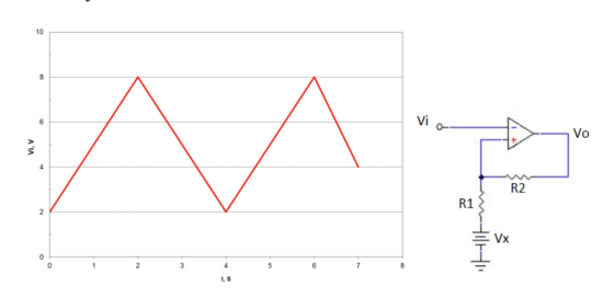
Determine the values of R1, R2, and Vx such that VTH = 6V and VTL = 4V (consider the voltage of saturation +,-Vsat = +,-15V). Once the above is done, determine the graph of the output voltage considering the input signal Vi shown below
Homework Answers


Add Answer to:
Determine the values of R1, R2, and Vx such that VTH = 6V and VTL =...
3) For the Bistable circuit shown, a) Derive expressions for the threshold voltages VTL and Vth...
 3) For the Bistable circuit shown, a) Derive expressions for the threshold voltages VTL and Vth in terms of the op- amp's saturation level L+, L_, R1, R2, R3, and V. b) Let L+ = -L_ = 7.5 V, V = 12.5 V, and R1 = 2 k.2. Find the values of R2 and R3 that result in VTL = +4.75 V and Vth = +5.25 V. OV R3 R2 w R w vo
Analyze and determine the equation of the output voltage of the next circuit. Considering the proposed input signal(Graph in red below), graph by hand Vo and indicate the maximum voltage in the graph,...
 Analyze and determine the equation of the output voltage of the next circuit. Considering the
proposed input signal(Graph in red below), graph by hand Vo and indicate the maximum voltage in the graph,
minimum voltage, time values where maximums, minimums and crossings are given by zero.
Consider that the saturation voltages are +,-Vsat = +,-15 VDC.
Vi R/2 opamp opamp 4 1 Vi 2 t, s 0 2 3 -2
Vi R/2 opamp opamp
4 1 Vi 2 t, s...
Analyze and determine the equation of the output voltage of the next circuit. Considering the
proposed input signal(Graph in red below), graph by hand Vo and indicate the maximum voltage in the graph,
minimum voltage, time values where maximums, minimums and crossings are given by zero.
Consider that the saturation voltages are +,-Vsat = +,-15 VDC.
Vi R/2 opamp opamp 4 1 Vi 2 t, s 0 2 3 -2
Vi R/2 opamp opamp
4 1 Vi 2 t, s...
Part "c" Please! Consider the circuit below. Assume that the only inductance of interest is the...
 Part "c" Please!
Consider the circuit below. Assume that the only inductance of interest is the load inductor L = 15mH connected to the output terminal. The resistors have the following values: R1 = 5kN, R2 = 2kN, R3 = 0.1kN, and RI, = 10kN. The supply voltage is Vs = 15V. Vs R2 R, vo R1 R3 Figure 6-1 It is known that the input voltage vị can be decomposed into two parts, a constant Vị and a small...
Part "c" Please!
Consider the circuit below. Assume that the only inductance of interest is the load inductor L = 15mH connected to the output terminal. The resistors have the following values: R1 = 5kN, R2 = 2kN, R3 = 0.1kN, and RI, = 10kN. The supply voltage is Vs = 15V. Vs R2 R, vo R1 R3 Figure 6-1 It is known that the input voltage vị can be decomposed into two parts, a constant Vị and a small...
i)draw the transafer charcheristics for this circuit? ii)Derive expressions for VTH and VTL? iii)Let L+ = - L- = 10 V, and R1=1 k Ω , choose R2 in order to get a hysteresis of 100mV width? iv).An engi...
 i)draw the transafer
charcheristics for this circuit?
ii)Derive expressions for VTH and VTL?
iii)Let L+ = - L- = 10 V, and R1=1 k Ω , choose R2 in order to
get a hysteresis of
100mV width?
iv).An engineer decided to modify the given circuit by
disconnecting the inverting
input of the op-amp from the ground and connecting it to a constant
voltage
source Vx. Derive expressions for VTH and VTL and Draw the transfer
characteristics in this case.?
Question...
i)draw the transafer
charcheristics for this circuit?
ii)Derive expressions for VTH and VTL?
iii)Let L+ = - L- = 10 V, and R1=1 k Ω , choose R2 in order to
get a hysteresis of
100mV width?
iv).An engineer decided to modify the given circuit by
disconnecting the inverting
input of the op-amp from the ground and connecting it to a constant
voltage
source Vx. Derive expressions for VTH and VTL and Draw the transfer
characteristics in this case.?
Question...
Please answer clearly Question 2 The amplifier shown in Figure 2 has the following parameters: Kn(W/L)-1 mA/V2, V-1 V Determine a) Voltage gain (Vo/vi) b) Input resistance (R) c) Output resistance (R...
 Please answer clearly
Question 2 The amplifier shown in Figure 2 has the following parameters: Kn(W/L)-1 mA/V2, V-1 V Determine a) Voltage gain (Vo/vi) b) Input resistance (R) c) Output resistance (Ro) d) Maximum output voltage swing so as the amplifier stays in saturation mode. Assume VDD-20 V, R1-2.5 ΚΩ, R2-1KQ, R3-0.5 ΚΩ, R4-5 MQ, R5_1ΜΩ. R4 R1 R5 R2 Ro R3
Question 2 The amplifier shown in Figure 2 has the following parameters: Kn(W/L)-1 mA/V2, V-1 V Determine a)...
Please answer clearly
Question 2 The amplifier shown in Figure 2 has the following parameters: Kn(W/L)-1 mA/V2, V-1 V Determine a) Voltage gain (Vo/vi) b) Input resistance (R) c) Output resistance (Ro) d) Maximum output voltage swing so as the amplifier stays in saturation mode. Assume VDD-20 V, R1-2.5 ΚΩ, R2-1KQ, R3-0.5 ΚΩ, R4-5 MQ, R5_1ΜΩ. R4 R1 R5 R2 Ro R3
Question 2 The amplifier shown in Figure 2 has the following parameters: Kn(W/L)-1 mA/V2, V-1 V Determine a)...
Cz 개2 Ci R1 Take RL = 20 kn, R1 = R2 10 An active network is representedas shown above. (a) Use ...
 Cz 개2 Ci R1 Take RL = 20 kn, R1 = R2 10 An active network is representedas shown above. (a) Use Multisim or PSpice to determine the frequency response of the network. (b) Obtain the equivalent passive network, i.e. an RLC circuit that will have the same frequency response. e2t u(t), find the output signal vo (t) of the (c) Given the input signal vs (t) passive network in (b). (d) Given the output signal vo (t) 4 sin...
The circuit 3-The circuit of problem # 2 is subjected to a small ac input by the signal generator. By neglecting the voltage drop across the coupling and bypass capacitors, determine the small signa...
 The circuit
3-The circuit of problem # 2 is subjected to a small ac input by the signal generator. By neglecting the voltage drop across the coupling and bypass capacitors, determine the small signal voltage gain Vo/ Vì = Avi , input resistance Ri-vi / ii and the output resistance Ro external to R Avi= Ri= , Ro The accompanying circuit shows a 4-resistor biased JFET transistor Determine the values of Rp and Rs so that the Q-point is equal...
The circuit
3-The circuit of problem # 2 is subjected to a small ac input by the signal generator. By neglecting the voltage drop across the coupling and bypass capacitors, determine the small signal voltage gain Vo/ Vì = Avi , input resistance Ri-vi / ii and the output resistance Ro external to R Avi= Ri= , Ro The accompanying circuit shows a 4-resistor biased JFET transistor Determine the values of Rp and Rs so that the Q-point is equal...
For the circuit of Figure 1, choose values for resistors R1, R2, and R3
 C.la For the circuit of Figure 1, choose values for resistors R1, R2, and R3(all resistances must be greater than one Kilo ohm). Given that the voltage source Vs1 = 8V and Vs2 = 10V determine the output voltage Vout. C.1b For the same resistor values Ri, R2, and Rs you chose in part C.la Given that the voltage source Vsi = 8V and Vs2 = 10V, use Figure 2(a) to determine the output voltage Vout/ and Figure 2(b) to determine the output voltage Vout2. Discussion:...
WA R3 W Consider the above circuit with indicated parameters and Rs.83.50, R1=20k0, R2=2020, RE1=428.30, RE2-5000,...
 WA R3 W Consider the above circuit with indicated parameters and Rs.83.50, R1=20k0, R2=2020, RE1=428.30, RE2-5000, RC=10, RL=5.0kg, B=39, VBE=0.8V, IVAL= 36 V and VT=20mv. For the following questions, do not do your own DC calculations - assume a hypothetical value for IC=4mA. (a) Calculate the input impedance of the amplifier, Ri. Answer: (b) Find the voltage gain vi/vs Answer: (c) Find the voltage gain vo/vi Answer: (b) Find the voltage gain vi/vs Answer: (c) Find the voltage gain vo/vi...
Please show all work Question 3 (3 points) R1 RL R2 R3 The circuit above has...
 Please show all work
Question 3 (3 points) R1 RL R2 R3 The circuit above has the following values: V 55 V. R1-120 Ω. R2-910 Ω and R3 = 100 Ω. Determine the Thevenin voltage and resistance (c) VTH-55.00 V and RTH " 206.02 Ω VTH = 48.59 V and RTH = 206.02 Ω VTH 55.00 V and RTH 106.02 0 VTH 48.56 V and RTH 106,022
Please show all work
Question 3 (3 points) R1 RL R2 R3 The circuit above has the following values: V 55 V. R1-120 Ω. R2-910 Ω and R3 = 100 Ω. Determine the Thevenin voltage and resistance (c) VTH-55.00 V and RTH " 206.02 Ω VTH = 48.59 V and RTH = 206.02 Ω VTH 55.00 V and RTH 106.02 0 VTH 48.56 V and RTH 106,022
 3) For the Bistable circuit shown, a) Derive expressions for the threshold voltages VTL and Vth in terms of the op- amp's saturation level L+, L_, R1, R2, R3, and V. b) Let L+ = -L_ = 7.5 V, V = 12.5 V, and R1 = 2 k.2. Find the values of R2 and R3 that result in VTL = +4.75 V and Vth = +5.25 V. OV R3 R2 w R w vo
 Analyze and determine the equation of the output voltage of the next circuit. Considering the
proposed input signal(Graph in red below), graph by hand Vo and indicate the maximum voltage in the graph,
minimum voltage, time values where maximums, minimums and crossings are given by zero.
Consider that the saturation voltages are +,-Vsat = +,-15 VDC.
Vi R/2 opamp opamp 4 1 Vi 2 t, s 0 2 3 -2
Vi R/2 opamp opamp
4 1 Vi 2 t, s...
Analyze and determine the equation of the output voltage of the next circuit. Considering the
proposed input signal(Graph in red below), graph by hand Vo and indicate the maximum voltage in the graph,
minimum voltage, time values where maximums, minimums and crossings are given by zero.
Consider that the saturation voltages are +,-Vsat = +,-15 VDC.
Vi R/2 opamp opamp 4 1 Vi 2 t, s 0 2 3 -2
Vi R/2 opamp opamp
4 1 Vi 2 t, s...
 Part "c" Please!
Consider the circuit below. Assume that the only inductance of interest is the load inductor L = 15mH connected to the output terminal. The resistors have the following values: R1 = 5kN, R2 = 2kN, R3 = 0.1kN, and RI, = 10kN. The supply voltage is Vs = 15V. Vs R2 R, vo R1 R3 Figure 6-1 It is known that the input voltage vị can be decomposed into two parts, a constant Vị and a small...
Part "c" Please!
Consider the circuit below. Assume that the only inductance of interest is the load inductor L = 15mH connected to the output terminal. The resistors have the following values: R1 = 5kN, R2 = 2kN, R3 = 0.1kN, and RI, = 10kN. The supply voltage is Vs = 15V. Vs R2 R, vo R1 R3 Figure 6-1 It is known that the input voltage vị can be decomposed into two parts, a constant Vị and a small...
 i)draw the transafer
charcheristics for this circuit?
ii)Derive expressions for VTH and VTL?
iii)Let L+ = - L- = 10 V, and R1=1 k Ω , choose R2 in order to
get a hysteresis of
100mV width?
iv).An engineer decided to modify the given circuit by
disconnecting the inverting
input of the op-amp from the ground and connecting it to a constant
voltage
source Vx. Derive expressions for VTH and VTL and Draw the transfer
characteristics in this case.?
Question...
i)draw the transafer
charcheristics for this circuit?
ii)Derive expressions for VTH and VTL?
iii)Let L+ = - L- = 10 V, and R1=1 k Ω , choose R2 in order to
get a hysteresis of
100mV width?
iv).An engineer decided to modify the given circuit by
disconnecting the inverting
input of the op-amp from the ground and connecting it to a constant
voltage
source Vx. Derive expressions for VTH and VTL and Draw the transfer
characteristics in this case.?
Question...
 Please answer clearly
Question 2 The amplifier shown in Figure 2 has the following parameters: Kn(W/L)-1 mA/V2, V-1 V Determine a) Voltage gain (Vo/vi) b) Input resistance (R) c) Output resistance (Ro) d) Maximum output voltage swing so as the amplifier stays in saturation mode. Assume VDD-20 V, R1-2.5 ΚΩ, R2-1KQ, R3-0.5 ΚΩ, R4-5 MQ, R5_1ΜΩ. R4 R1 R5 R2 Ro R3
Question 2 The amplifier shown in Figure 2 has the following parameters: Kn(W/L)-1 mA/V2, V-1 V Determine a)...
Please answer clearly
Question 2 The amplifier shown in Figure 2 has the following parameters: Kn(W/L)-1 mA/V2, V-1 V Determine a) Voltage gain (Vo/vi) b) Input resistance (R) c) Output resistance (Ro) d) Maximum output voltage swing so as the amplifier stays in saturation mode. Assume VDD-20 V, R1-2.5 ΚΩ, R2-1KQ, R3-0.5 ΚΩ, R4-5 MQ, R5_1ΜΩ. R4 R1 R5 R2 Ro R3
Question 2 The amplifier shown in Figure 2 has the following parameters: Kn(W/L)-1 mA/V2, V-1 V Determine a)...
 Cz 개2 Ci R1 Take RL = 20 kn, R1 = R2 10 An active network is representedas shown above. (a) Use Multisim or PSpice to determine the frequency response of the network. (b) Obtain the equivalent passive network, i.e. an RLC circuit that will have the same frequency response. e2t u(t), find the output signal vo (t) of the (c) Given the input signal vs (t) passive network in (b). (d) Given the output signal vo (t) 4 sin...
 The circuit
3-The circuit of problem # 2 is subjected to a small ac input by the signal generator. By neglecting the voltage drop across the coupling and bypass capacitors, determine the small signal voltage gain Vo/ Vì = Avi , input resistance Ri-vi / ii and the output resistance Ro external to R Avi= Ri= , Ro The accompanying circuit shows a 4-resistor biased JFET transistor Determine the values of Rp and Rs so that the Q-point is equal...
The circuit
3-The circuit of problem # 2 is subjected to a small ac input by the signal generator. By neglecting the voltage drop across the coupling and bypass capacitors, determine the small signal voltage gain Vo/ Vì = Avi , input resistance Ri-vi / ii and the output resistance Ro external to R Avi= Ri= , Ro The accompanying circuit shows a 4-resistor biased JFET transistor Determine the values of Rp and Rs so that the Q-point is equal...
 C.la For the circuit of Figure 1, choose values for resistors R1, R2, and R3(all resistances must be greater than one Kilo ohm). Given that the voltage source Vs1 = 8V and Vs2 = 10V determine the output voltage Vout. C.1b For the same resistor values Ri, R2, and Rs you chose in part C.la Given that the voltage source Vsi = 8V and Vs2 = 10V, use Figure 2(a) to determine the output voltage Vout/ and Figure 2(b) to determine the output voltage Vout2. Discussion:...
 WA R3 W Consider the above circuit with indicated parameters and Rs.83.50, R1=20k0, R2=2020, RE1=428.30, RE2-5000, RC=10, RL=5.0kg, B=39, VBE=0.8V, IVAL= 36 V and VT=20mv. For the following questions, do not do your own DC calculations - assume a hypothetical value for IC=4mA. (a) Calculate the input impedance of the amplifier, Ri. Answer: (b) Find the voltage gain vi/vs Answer: (c) Find the voltage gain vo/vi Answer: (b) Find the voltage gain vi/vs Answer: (c) Find the voltage gain vo/vi...
 Please show all work
Question 3 (3 points) R1 RL R2 R3 The circuit above has the following values: V 55 V. R1-120 Ω. R2-910 Ω and R3 = 100 Ω. Determine the Thevenin voltage and resistance (c) VTH-55.00 V and RTH " 206.02 Ω VTH = 48.59 V and RTH = 206.02 Ω VTH 55.00 V and RTH 106.02 0 VTH 48.56 V and RTH 106,022
Please show all work
Question 3 (3 points) R1 RL R2 R3 The circuit above has the following values: V 55 V. R1-120 Ω. R2-910 Ω and R3 = 100 Ω. Determine the Thevenin voltage and resistance (c) VTH-55.00 V and RTH " 206.02 Ω VTH = 48.59 V and RTH = 206.02 Ω VTH 55.00 V and RTH 106.02 0 VTH 48.56 V and RTH 106,022
Most questions answered within 3 hours.
-
Recently I purchased a second vehicle for our family. The
vehicle we had was too small...
asked 5 minutes ago -
Two narrow, parallel slits separated by 0.850 mm are illuminated
by 570-nm light, and the viewing...
asked 13 minutes ago -
Write a balanced equation for the double-replacement
precipitation reaction described, using the smallest possible
integer coefficients....
asked 12 minutes ago -
Would You expect the analysis produced by the Legislative
Analyst’s Office to be more or less...
asked 29 minutes ago -
How configuring websites to use a common NFS share could
strengthen business continuity efforts
asked 30 minutes ago -
Arrange the following aqueous solutions in order of increasing
boiling point: 0.25 m NaCl (sodium chloride)...
asked 31 minutes ago -
calculate the mass of forsterite (Mg2SiO4) that contains a
million (1.00•10^6) oxygen
asked 54 minutes ago -
A heat engine has an efficiency of 0.48. Initially,
the engine performs net work W per...
asked 44 minutes ago -
identify the effect on the financial statement on the
following senarios:
b) the clients business mainly...
asked 41 minutes ago -
Whenever two Apollo astronauts were on the surface of the Moon,
a third astronaut orbited the...
asked 51 minutes ago -
Suppose that Marriott’s production process is characterized by
constant returns to scale at all output levels....
asked 51 minutes ago -
If a customer places a buy order for one millisecond only on an
electronic limit order...
asked 59 minutes ago