
Homework Answers


Add Answer to:
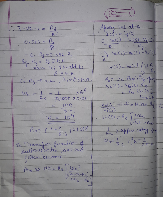
9. Design a second-order Butterworth low-pass filter with a 0.01 ?F capacitor and a 10 knesstor...
Design a second-order Butterworth low-pass filter to satisfy the specifications a. The dc gain is...
 Design a second-order Butterworth low-pass filter to satisfy the specifications a. The dc gain is unity (zero dB); b. The gain is no smaller than -1 dB for frequencies between 0 and 2,000 Hz; and c. The gain is no larger than -40 dB for frequencies larger than 40 kHz. Determine a circuit realization as a series RLC low-pass filter. Pick reasonable values of R, L, and C.
Design a second-order Butterworth low-pass filter to satisfy the specifications a. The...
Design a second-order Butterworth low-pass filter to satisfy the specifications a. The dc gain is unity (zero dB); b. The gain is no smaller than -1 dB for frequencies between 0 and 2,000 Hz; and c. The gain is no larger than -40 dB for frequencies larger than 40 kHz. Determine a circuit realization as a series RLC low-pass filter. Pick reasonable values of R, L, and C.
Design a second-order Butterworth low-pass filter to satisfy the specifications a. The...
Design a low-pass Butterworth filter of the lowest order possible that has a cutoff frequency of ...
Design a low-pass Butterworth filter of the lowest order possible that has a cutoff frequency of 100 kHz and a no more then -30 dB at 600kHz. Use as many 50Ω resistors as possible. Draw the circuit.
Design a second-order Butterworth low-pass filter with a DC gain of 0 dB and a -3...
Design a second-order Butterworth low-pass filter with a DC gain of 0 dB and a -3 dB frequency of 5.24 kHz. (include circuit design w/ component values)
Design a fourth order low pass Butterworth filter with a cutoff frequency of 2 kHz and...
Design a fourth order low pass Butterworth filter with a cutoff frequency of 2 kHz and draw the frequency response for the filter.
Design a second order IIR Butterworth low pass digital filter with a cutoff frequency of 500...
Design a second order IIR Butterworth low pass digital filter with a cutoff frequency of 500 Hz and a sampling frequency of 10,000 Hz using bilinear transformation then find the following: The output (response) due to the following inputs: Sinusoidal signal with a frequency of 100Hz. Sinusoidal signal with a frequency of 500Hz. Sinusoidal signal with a frequency of 2000Hz. Repeat (a) above for a 6thorder Butterworth filter
Using filterDesigner in MATLAB, design a second order low pass IIR Butterworth filter whose sampling frequency...
Using filterDesigner in MATLAB, design a second order low pass IIR Butterworth filter whose sampling frequency (Fs) is 1 kHz and cutoff frequency (Fc) is 10 Hz. Find the numerator and denominator coefficients. Write its transfer function H(z) = Y(z) / X(z). Write its difference function y(k). Draw (copy from Filter Designer) the magnitude response plot. Draw (copy from Filter Designer) the phase response plot. Draw (copy from Filter Designer) the impulse response plot.
Design a -40 dB second order low pass active filter for a cut-off frequency of 3...
Design a -40 dB second order low pass active filter for a cut-off frequency of 3 kHz. You are free to choose the values of resistors and capacitors.
just do 4 , 3 is solved 3. Use a Bilinear Transform to design a Butterworth low-pass filter which satisfies the filter specifications: Pass band: -1Ss0 for 0sf s0.2 Stop band: (e/40 for 0.35sf s0....
 just do 4 , 3 is solved
3. Use a Bilinear Transform to design a Butterworth low-pass filter which satisfies the filter specifications: Pass band: -1Ss0 for 0sf s0.2 Stop band: (e/40 for 0.35sf s0.s Transition Band: 0.2<f<0.35 Sampling Frequency: 10 kHz a. (3) Determine the stop-band and pass-band frequencies, Fstop and Fpas, in kHz. b. (3) Calculate the fater order, n, which is necessary to obtain the desired filter specifications. (3) Calculate the corner frequency, Fe, if you want...
just do 4 , 3 is solved
3. Use a Bilinear Transform to design a Butterworth low-pass filter which satisfies the filter specifications: Pass band: -1Ss0 for 0sf s0.2 Stop band: (e/40 for 0.35sf s0.s Transition Band: 0.2<f<0.35 Sampling Frequency: 10 kHz a. (3) Determine the stop-band and pass-band frequencies, Fstop and Fpas, in kHz. b. (3) Calculate the fater order, n, which is necessary to obtain the desired filter specifications. (3) Calculate the corner frequency, Fe, if you want...
Using filterDesigner in MATLAB, design a second order low pass IIR Butterworth filter whose sampling frequency (Fs) is 1...
Using filterDesigner in MATLAB, design a second order low pass IIR Butterworth filter whose sampling frequency (Fs) is 1 kHz and cutoff frequency (Fc) is 10 Hz. Find the numerator and denominator coefficients. Write its transfer function H(z) = Y(z) / X(z). Write its difference function y(k). Draw (copy from Filter Designer) the magnitude response plot. Draw (copy from Filter Designer) the phase response plot. Draw (copy from Filter Designer) the impulse response plot.
QUESTION 6 Зро Design a second-order IIR digital low-pass filter using Butterworth approximation....
 QUESTION 6 Зро Design a second-order IIR digital low-pass filter using Butterworth approximation. Use the bilinear transformation to convert the analogue fiter to a digital one (choose the sampling period T- 2 s and the cut-off frequency as 1 rad/'s). Express the digital transfer function of the filter H(z) as: In the box below, provide the numerical answer for b1. [Note: Don't normalise the transfer func on, i.e. b0 # 1). r98111acontentid1837836_1&step QUESTION 7 Windowing based FIR filter design techniques...
 Design a second-order Butterworth low-pass filter to satisfy the specifications a. The dc gain is unity (zero dB); b. The gain is no smaller than -1 dB for frequencies between 0 and 2,000 Hz; and c. The gain is no larger than -40 dB for frequencies larger than 40 kHz. Determine a circuit realization as a series RLC low-pass filter. Pick reasonable values of R, L, and C.
Design a second-order Butterworth low-pass filter to satisfy the specifications a. The...
Design a second-order Butterworth low-pass filter to satisfy the specifications a. The dc gain is unity (zero dB); b. The gain is no smaller than -1 dB for frequencies between 0 and 2,000 Hz; and c. The gain is no larger than -40 dB for frequencies larger than 40 kHz. Determine a circuit realization as a series RLC low-pass filter. Pick reasonable values of R, L, and C.
Design a second-order Butterworth low-pass filter to satisfy the specifications a. The...
 just do 4 , 3 is solved
3. Use a Bilinear Transform to design a Butterworth low-pass filter which satisfies the filter specifications: Pass band: -1Ss0 for 0sf s0.2 Stop band: (e/40 for 0.35sf s0.s Transition Band: 0.2<f<0.35 Sampling Frequency: 10 kHz a. (3) Determine the stop-band and pass-band frequencies, Fstop and Fpas, in kHz. b. (3) Calculate the fater order, n, which is necessary to obtain the desired filter specifications. (3) Calculate the corner frequency, Fe, if you want...
just do 4 , 3 is solved
3. Use a Bilinear Transform to design a Butterworth low-pass filter which satisfies the filter specifications: Pass band: -1Ss0 for 0sf s0.2 Stop band: (e/40 for 0.35sf s0.s Transition Band: 0.2<f<0.35 Sampling Frequency: 10 kHz a. (3) Determine the stop-band and pass-band frequencies, Fstop and Fpas, in kHz. b. (3) Calculate the fater order, n, which is necessary to obtain the desired filter specifications. (3) Calculate the corner frequency, Fe, if you want...
 QUESTION 6 Зро Design a second-order IIR digital low-pass filter using Butterworth approximation. Use the bilinear transformation to convert the analogue fiter to a digital one (choose the sampling period T- 2 s and the cut-off frequency as 1 rad/'s). Express the digital transfer function of the filter H(z) as: In the box below, provide the numerical answer for b1. [Note: Don't normalise the transfer func on, i.e. b0 # 1). r98111acontentid1837836_1&step QUESTION 7 Windowing based FIR filter design techniques...
Most questions answered within 3 hours.
-
Provide a summary/reflection of what you gleaned of how law
enforcement is effect by Unconventional Weapons...
asked 20 minutes ago -
From the following heats of combustion,
CH3OH(l) + 3/2O2(g) → CO2(g) +
2H2O(l)
ΔHorxn = –726.4...
asked 13 minutes ago -
Floating Point Representation
Consider a computer that stores information using 10 bits words.
The first bit...
asked 42 minutes ago -
. The theoretical weight percent of carbon in (CH3)3N is:
A. 20.32% B. 81.95% C. 9.97%...
asked 35 minutes ago -
The rate of a certain reaction is given by the following rate
law:
rate = k[H2][I2]...
asked 30 minutes ago -
A 10,000 uF capacitor is in series with a 1 uH inductor. What is
Zeq of...
asked 34 minutes ago -
Draw the molecular orbital diagram for O2-
(oxygen molecule with a negative charge).
asked 51 minutes ago -
Of all the different weapons discussed in this chapter that make
up CBRNE,
Which group do...
asked 49 minutes ago -
Given the following JavaScript code, what will be displayed on
the web page?
var x =...
asked 59 minutes ago -
The cynics, skeptics, epicureans, & stoics were most
philosophies that dealt with:
a. the physical...
asked 1 hour ago -
The hydronium ion concentration of an aqueous solution of 0.333
M trimethylamine (a weak base with...
asked 1 hour ago -
A buffer is prepared by partially titrating 50.00 mL of 0.964 M
benzoic acid using 0,100...
asked 1 hour ago