
Homework Answers
 please
rate
please
rate
Add Answer to:
1.47 A load P is supported as shown by a steel pin that has been inserted...
A load P is supported as shown by a steel pin that has been inserted in...
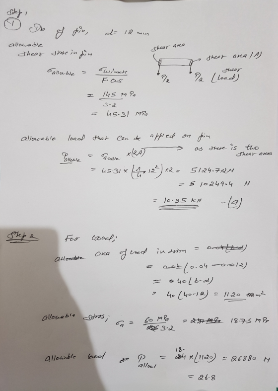
 A load P is supported as shown by a steel pin that has been inserted in a short wooden member hanging from the ceiling. The ultimate strength of the wood used is 60 MPa in tension and 7.5 MPa in shear, while the ultimate strength of the steel is 145 MPa in shear. The diameter of the pin is d= 18 mm and the magnitude of the load is P= 20 KN. NOTE: This is a multi-part question. Once an...
1.51 In the steel structure shown, a 6-mm-diameter pin is used at C and 10-mm-diameter pins...
 1.51 In the steel structure shown, a 6-mm-diameter pin is used at C and 10-mm-diameter pins are used at B and D. The ultimate shearing stress is 150 MPa at all connections, and the ultimate normal stress is 400 MPa in link BD. Knowing that a factor of safety of 3.0 is desired, determine the largest load P that can be applied at A. Note that ink BD is not reinforced around the pin holes Front view 18 mm Side...
Rigid bar is supported by a pin-connected axial bar (1) and a pin connection at C...
 Rigid bar is supported by a pin-connected axial bar (1) and a pin connection at C as shown in Figure Q1. Member (1) is a 20 mm wide by 9 mm thick rectangular bar made of Steel Alloys (A992). The total strain in bar (1) is measured as 925 ue (925x10°). The pin at C has an ultimate shear strength of ty = 345MPa. Determine: (a) The axial force in member (1). [9 marks] (b) The factor of safety in...
Problem 4 (3pts) The beam AB is supported by a single-shear pin connection at joint A...
 Problem 4 (3pts) The beam AB is supported by a single-shear pin connection at joint A and by a double-shear connection to member (1) at joint B. Member (1) is connected to the support at C with a double-shear pin connection. Member (1) has a cross-sectional area of 100 mm and a yield strength of 340 MPa. The pins at A, B, and C each have a diameter of 12 mm, and an ultimate shear strength of 270 MPa. Specifications...
In the steel structure shown, a 6-mm-diameter pin is used at C and 10-mm-diameter pins are...
 In the steel structure shown, a 6-mm-diameter pin is used at C and 10-mm-diameter pins are used at B and D. The ultimate shearing stress is 159 MPa at all connections, and the ultimate normal stress is 400 MPa in link BD. Knowing that a factor of safety of 3.0 is desired, determine the largest load P that can be applied at A. Note that link BD is not reinforced around the pin holes. (Round the final answer to three...
1.52 Solve Prob. 1.51, assuming that the structure has been redesigned to use 16-in.-diameter pins at...
 1.52 Solve Prob. 1.51, assuming that the structure has been redesigned to use 16-in.-diameter pins at A and C as well as at B and that no other changes have been made. A in. 8 in. B C 4 in. 6 in. Fig.P1.51 1.51 Link AC is made of a steel with a 65-ksi ultimate normal stress and has a 2-in. uniform rectangular cross section. It is connected to a support at A and to member BCD at C by-in.-diameter...
Label Given, Find , and Solution PLEASE 1.18 A load P is applied to a steel...
 Label Given, Find , and Solution PLEASE
1.18 A load P is applied to a steel rod supported as shown by an alu- minum plate into which a 12-mm-diameter hole has been drilled Knowing that the shearing stress must not exceed 180 MPa in the steel rod and 70 MPa in the aluminum plate, determine the larg- est load P that can be applied to the rod. 40 mm 10 mm 8 mm 12 mm Fig. P1.18
Label Given, Find , and Solution PLEASE
1.18 A load P is applied to a steel rod supported as shown by an alu- minum plate into which a 12-mm-diameter hole has been drilled Knowing that the shearing stress must not exceed 180 MPa in the steel rod and 70 MPa in the aluminum plate, determine the larg- est load P that can be applied to the rod. 40 mm 10 mm 8 mm 12 mm Fig. P1.18
4. (15pts) In the structure shown in Fig. 1, an 8-mm-diameter pin is used at A,...
 4. (15pts) In the structure shown in Fig. 1, an 8-mm-diameter pin is used at A, and 12-mm-diameter pins used at B and D. Knowing that the ultimate shearing stress is 100 MPa at all connections and that the ultimate normal stress is 250 MPa in each of the two links jointing B and D, determine the allowable load P if an overall factor of safety of 3.0 is desired. Top view -200 mm-fe180 mm-12 mm B с Smm 20...
Beam AB is supported as shown in the figure. Tie rod(1) has a diameter of...
 Beam AB is supported as shown in the figure. Tie rod
(1) has a diameter of 60 mm, and it is attached at B and C with 24 mm diameter double-shear pin connections. The pin
connection at A consists of a 37 mm diameter single-shear
pin. The pins at A, B, and C each have
an ultimate shear strength of 500 MPa, and tie rod (1) has a yield
strength of 280 MPa. A uniformly distributed load of w is applied
to...
Beam AB is supported as shown in the figure. Tie rod
(1) has a diameter of 60 mm, and it is attached at B and C with 24 mm diameter double-shear pin connections. The pin
connection at A consists of a 37 mm diameter single-shear
pin. The pins at A, B, and C each have
an ultimate shear strength of 500 MPa, and tie rod (1) has a yield
strength of 280 MPa. A uniformly distributed load of w is applied
to...
In the figure, the rigid member ABDE is supported at A by a single shear pin...
 In the figure, the rigid member ABDE is supported at
A by a single shear pin connection and at B by a
tie rod (1). The tie rod is attached at B and C
with double shear pin connections. The pins at A,
B, and C each have an ultimate shear strength of
84 ksi, and tie rod (1) has a yield strength of 63 ksi. A
concentrated load of P = 20 kips is applied perpendicular
to DE, as...
In the figure, the rigid member ABDE is supported at
A by a single shear pin connection and at B by a
tie rod (1). The tie rod is attached at B and C
with double shear pin connections. The pins at A,
B, and C each have an ultimate shear strength of
84 ksi, and tie rod (1) has a yield strength of 63 ksi. A
concentrated load of P = 20 kips is applied perpendicular
to DE, as...
 A load P is supported as shown by a steel pin that has been inserted in a short wooden member hanging from the ceiling. The ultimate strength of the wood used is 60 MPa in tension and 7.5 MPa in shear, while the ultimate strength of the steel is 145 MPa in shear. The diameter of the pin is d= 18 mm and the magnitude of the load is P= 20 KN. NOTE: This is a multi-part question. Once an...
 1.51 In the steel structure shown, a 6-mm-diameter pin is used at C and 10-mm-diameter pins are used at B and D. The ultimate shearing stress is 150 MPa at all connections, and the ultimate normal stress is 400 MPa in link BD. Knowing that a factor of safety of 3.0 is desired, determine the largest load P that can be applied at A. Note that ink BD is not reinforced around the pin holes Front view 18 mm Side...
 Rigid bar is supported by a pin-connected axial bar (1) and a pin connection at C as shown in Figure Q1. Member (1) is a 20 mm wide by 9 mm thick rectangular bar made of Steel Alloys (A992). The total strain in bar (1) is measured as 925 ue (925x10°). The pin at C has an ultimate shear strength of ty = 345MPa. Determine: (a) The axial force in member (1). [9 marks] (b) The factor of safety in...
 Problem 4 (3pts) The beam AB is supported by a single-shear pin connection at joint A and by a double-shear connection to member (1) at joint B. Member (1) is connected to the support at C with a double-shear pin connection. Member (1) has a cross-sectional area of 100 mm and a yield strength of 340 MPa. The pins at A, B, and C each have a diameter of 12 mm, and an ultimate shear strength of 270 MPa. Specifications...
 In the steel structure shown, a 6-mm-diameter pin is used at C and 10-mm-diameter pins are used at B and D. The ultimate shearing stress is 159 MPa at all connections, and the ultimate normal stress is 400 MPa in link BD. Knowing that a factor of safety of 3.0 is desired, determine the largest load P that can be applied at A. Note that link BD is not reinforced around the pin holes. (Round the final answer to three...
 1.52 Solve Prob. 1.51, assuming that the structure has been redesigned to use 16-in.-diameter pins at A and C as well as at B and that no other changes have been made. A in. 8 in. B C 4 in. 6 in. Fig.P1.51 1.51 Link AC is made of a steel with a 65-ksi ultimate normal stress and has a 2-in. uniform rectangular cross section. It is connected to a support at A and to member BCD at C by-in.-diameter...
 Label Given, Find , and Solution PLEASE
1.18 A load P is applied to a steel rod supported as shown by an alu- minum plate into which a 12-mm-diameter hole has been drilled Knowing that the shearing stress must not exceed 180 MPa in the steel rod and 70 MPa in the aluminum plate, determine the larg- est load P that can be applied to the rod. 40 mm 10 mm 8 mm 12 mm Fig. P1.18
Label Given, Find , and Solution PLEASE
1.18 A load P is applied to a steel rod supported as shown by an alu- minum plate into which a 12-mm-diameter hole has been drilled Knowing that the shearing stress must not exceed 180 MPa in the steel rod and 70 MPa in the aluminum plate, determine the larg- est load P that can be applied to the rod. 40 mm 10 mm 8 mm 12 mm Fig. P1.18
 4. (15pts) In the structure shown in Fig. 1, an 8-mm-diameter pin is used at A, and 12-mm-diameter pins used at B and D. Knowing that the ultimate shearing stress is 100 MPa at all connections and that the ultimate normal stress is 250 MPa in each of the two links jointing B and D, determine the allowable load P if an overall factor of safety of 3.0 is desired. Top view -200 mm-fe180 mm-12 mm B с Smm 20...
 Beam AB is supported as shown in the figure. Tie rod
(1) has a diameter of 60 mm, and it is attached at B and C with 24 mm diameter double-shear pin connections. The pin
connection at A consists of a 37 mm diameter single-shear
pin. The pins at A, B, and C each have
an ultimate shear strength of 500 MPa, and tie rod (1) has a yield
strength of 280 MPa. A uniformly distributed load of w is applied
to...
Beam AB is supported as shown in the figure. Tie rod
(1) has a diameter of 60 mm, and it is attached at B and C with 24 mm diameter double-shear pin connections. The pin
connection at A consists of a 37 mm diameter single-shear
pin. The pins at A, B, and C each have
an ultimate shear strength of 500 MPa, and tie rod (1) has a yield
strength of 280 MPa. A uniformly distributed load of w is applied
to...
 In the figure, the rigid member ABDE is supported at
A by a single shear pin connection and at B by a
tie rod (1). The tie rod is attached at B and C
with double shear pin connections. The pins at A,
B, and C each have an ultimate shear strength of
84 ksi, and tie rod (1) has a yield strength of 63 ksi. A
concentrated load of P = 20 kips is applied perpendicular
to DE, as...
In the figure, the rigid member ABDE is supported at
A by a single shear pin connection and at B by a
tie rod (1). The tie rod is attached at B and C
with double shear pin connections. The pins at A,
B, and C each have an ultimate shear strength of
84 ksi, and tie rod (1) has a yield strength of 63 ksi. A
concentrated load of P = 20 kips is applied perpendicular
to DE, as...
Most questions answered within 3 hours.
-
1. List the features used to classify leaf
types.
2. List some characteristics that are shared...
asked 1 minute ago -
The three elements of Value Proposition, Key Customers, and
Capabilities operate within an environment. Which of...
asked 3 minutes ago -
Katelynn, a physician, earns $200,000 from her medical practice
in the current year. She receives $45,000...
asked 11 minutes ago -
Each row of the table below describes an aqueous solution at
25°C
.
The second column...
asked 15 minutes ago -
A horizontal wire is at y = 0. Current travels in the +x
direction. The magnetic...
asked 16 minutes ago -
Let X be a continuous random variable whose PDF is Let X be a
continuous random...
asked 37 minutes ago -
Martinez Company’s relevant range of production is 7,500 units
to 12,500 units. When it produces and...
asked 35 minutes ago -
A football with a mass of 1.2 kg is kicked from ground level to
a height...
asked 40 minutes ago -
Remember: Changes in supply determinants shift supply, and
changes in demand determinants shift demand. We say...
asked 39 minutes ago -
Why is the answer b), for this question? I came up with C) for
my incorrect...
asked 45 minutes ago -
Suppose that you know that in the population of full-time
employees in the United States, the...
asked 1 hour ago -
This experiment was designed originally to sample various meat and carcass quality
aspects of Ontario pigs...
asked 1 hour ago