
Homework Answers

![© DC gains = odB IHCVA) |- k Viet? dc gain at s=0 9600 J Hope 1 Hcpio)] = k & Do gain to do a B . gain in dB + 20log k zo / K](http://img.homeworklib.com/questions/173483d0-77d5-11eb-b4ad-31d62544e0fd.png?x-oss-process=image/resize,w_560)

 please give ?
Thank you
Add Answer to:
a) Insert a resistor R3 in series with the feedback capacitor C in the low pass...
Assuming an ideal op-amp find the 3dB frequency of the circuit, if R1=1.8 K2, R2=10.9 KQ,...
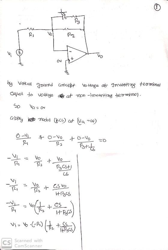
 Assuming an ideal op-amp find the 3dB frequency of the circuit, if R1=1.8 K2, R2=10.9 KQ, R3=20 K., and C=5 nF. HH с R2 Answer: orad/s R1 Vw R3 Consider the above circuit with the component values: R1=1.8 KO, R2=10.9 KO, R3=20 KQ and C=5 nF. Find the DC gain of the circuit. Answer: Consider the above circuit with the component values: R1=10.9 K2, R2= 795.77 2, R3=20 K, and C=100 nF. Find the angle of the transfer function in...
Design a second-order Butterworth low-pass filter to satisfy the specifications a. The dc gain is...
 Design a second-order Butterworth low-pass filter to satisfy the specifications a. The dc gain is unity (zero dB); b. The gain is no smaller than -1 dB for frequencies between 0 and 2,000 Hz; and c. The gain is no larger than -40 dB for frequencies larger than 40 kHz. Determine a circuit realization as a series RLC low-pass filter. Pick reasonable values of R, L, and C.
Design a second-order Butterworth low-pass filter to satisfy the specifications a. The...
Design a second-order Butterworth low-pass filter to satisfy the specifications a. The dc gain is unity (zero dB); b. The gain is no smaller than -1 dB for frequencies between 0 and 2,000 Hz; and c. The gain is no larger than -40 dB for frequencies larger than 40 kHz. Determine a circuit realization as a series RLC low-pass filter. Pick reasonable values of R, L, and C.
Design a second-order Butterworth low-pass filter to satisfy the specifications a. The...
Assuming an ideal op-amp find the 3dB frequency of the circuit, if R1=2.4 KS2, R2=13.4 K2,...
 Assuming an ideal op-amp find the 3dB frequency of the circuit, if R1=2.4 KS2, R2=13.4 K2, R3=20 KS2, and C=5 nF. HH C R2 R1 + Vi(jw) Vo R3 IH Answer: rad/s Consider the above circuit with the component values: R1=2.4 K12, R2=13.4 KS, R3=20 KN and C=5 nF. Find the DC gain of the circuit. Answer: Consider the above circuit with the component values: R1=13.4 KS, R2= 795.77 12, R3=20 K12, and C=100 nF. Find the angle of the...
Solve the next problems The next circuit allows signals to pass in a range from 12KHz...
 Solve the next problems
The next circuit allows signals to pass in a range from 12KHz to 20kHz. a) calculate the value of the components for all resistors use 10k b) draw the bode didgras C21 laset R1 u For the previous circuit, calculate the frequency range to be passed and the bandwidth gain in dB in R1 = 500l2, R2=30K2,01 = 100 nF and C2= 20 nF and: The filter shown below is used for a robotic manipulator to...
Solve the next problems
The next circuit allows signals to pass in a range from 12KHz to 20kHz. a) calculate the value of the components for all resistors use 10k b) draw the bode didgras C21 laset R1 u For the previous circuit, calculate the frequency range to be passed and the bandwidth gain in dB in R1 = 500l2, R2=30K2,01 = 100 nF and C2= 20 nF and: The filter shown below is used for a robotic manipulator to...
Design a second-order Butterworth low-pass filter with a DC gain of 0 dB and a -3...
Design a second-order Butterworth low-pass filter with a DC gain of 0 dB and a -3 dB frequency of 5.24 kHz. (include circuit design w/ component values)
2. A high pass filter is built using a 5k resistor and 200 pF capacitor. a....
 2. A high pass filter is built using a 5k resistor and 200 pF capacitor. a. Draw the circuit b. Calculate the time constant for the circuit c. What is the critical frequency (in rad/s) for the circuit? d. What is the critical frequency (in Hz) for the circuit? e. What is the attenuation for a 30 kHz signal? f. What is the attenuation for a 300 kHz signal? g. What is the 30 kHz attenuation in dB?
A) Design a low-pass filter using the given circuitry with a cut-off value of 1 kHz and plot the ...
 a) Design a low-pass filter using the given circuitry with a cut-off value of 1 kHz and plot the frequency response curve on the given axes 1.0 0.7 0.5 in out 0.0 101 102 103 104 10s Hz b) Design a band-pass filter using the given circuitry with a bandwidth of 500 Hz and a lower cut-off value of 100 Hz, and draw the frequency response curve. Keep all resistors at the same value (i.e. Ri-R-R3-R4). 1.0 0.7 0.5 0.0...
C, V. Low-pass High-pass Procedure: Design the following filters and be certain to provide the co...
 C, V. Low-pass High-pass Procedure: Design the following filters and be certain to provide the component values you used in a table like those shown on the third page. Record your calculations because they will be requested in the lab report. To make the lab simpler let the input resistor Ri be the same for all stages. In this particular case the loading effects from cascading the op-amp circuits will have little influence on the overall gain. Refer to your...
For the low-pass filter circuit shown in Fig 2 200mH 3k Ω out in Fig 2...
 For the low-pass filter circuit shown in Fig 2 200mH 3k Ω out in Fig 2 (i) (ii) (iii) Write an expression for the transfer function of the circuit State the value of the dc gain of the filter circuit in dB Calculate the cutoff frequency of the filter b. Sketch the frequency response of the voltage gain and phase shift for the filter shown in Fig 2. Show all the values and required information in both graphs Magnitude Frequency...
In the series RC circuit below, with R -6.1 k ohms& C 72.5 nF, at what angular frequency [rad/s] ...
 In the series RC circuit below, with R -6.1 k ohms& C 72.5 nF, at what angular frequency [rad/s] does the capacitor AC voltage reduce to its DC value (accurate to 1%)? C output Answer: In the series RC circuit below, with R-1.2 k ohms & C 92.8 nF, calculate the magnitude of the voltage 'gain' of the circuit (Vout/ Vsl), for a driving frequency of 0.1 kHz, to 1% accuracy. Coutput Answer For a series RLC circuit as shown...
 Assuming an ideal op-amp find the 3dB frequency of the circuit, if R1=1.8 K2, R2=10.9 KQ, R3=20 K., and C=5 nF. HH с R2 Answer: orad/s R1 Vw R3 Consider the above circuit with the component values: R1=1.8 KO, R2=10.9 KO, R3=20 KQ and C=5 nF. Find the DC gain of the circuit. Answer: Consider the above circuit with the component values: R1=10.9 K2, R2= 795.77 2, R3=20 K, and C=100 nF. Find the angle of the transfer function in...
 Design a second-order Butterworth low-pass filter to satisfy the specifications a. The dc gain is unity (zero dB); b. The gain is no smaller than -1 dB for frequencies between 0 and 2,000 Hz; and c. The gain is no larger than -40 dB for frequencies larger than 40 kHz. Determine a circuit realization as a series RLC low-pass filter. Pick reasonable values of R, L, and C.
Design a second-order Butterworth low-pass filter to satisfy the specifications a. The...
Design a second-order Butterworth low-pass filter to satisfy the specifications a. The dc gain is unity (zero dB); b. The gain is no smaller than -1 dB for frequencies between 0 and 2,000 Hz; and c. The gain is no larger than -40 dB for frequencies larger than 40 kHz. Determine a circuit realization as a series RLC low-pass filter. Pick reasonable values of R, L, and C.
Design a second-order Butterworth low-pass filter to satisfy the specifications a. The...
 Assuming an ideal op-amp find the 3dB frequency of the circuit, if R1=2.4 KS2, R2=13.4 K2, R3=20 KS2, and C=5 nF. HH C R2 R1 + Vi(jw) Vo R3 IH Answer: rad/s Consider the above circuit with the component values: R1=2.4 K12, R2=13.4 KS, R3=20 KN and C=5 nF. Find the DC gain of the circuit. Answer: Consider the above circuit with the component values: R1=13.4 KS, R2= 795.77 12, R3=20 K12, and C=100 nF. Find the angle of the...
 Solve the next problems
The next circuit allows signals to pass in a range from 12KHz to 20kHz. a) calculate the value of the components for all resistors use 10k b) draw the bode didgras C21 laset R1 u For the previous circuit, calculate the frequency range to be passed and the bandwidth gain in dB in R1 = 500l2, R2=30K2,01 = 100 nF and C2= 20 nF and: The filter shown below is used for a robotic manipulator to...
Solve the next problems
The next circuit allows signals to pass in a range from 12KHz to 20kHz. a) calculate the value of the components for all resistors use 10k b) draw the bode didgras C21 laset R1 u For the previous circuit, calculate the frequency range to be passed and the bandwidth gain in dB in R1 = 500l2, R2=30K2,01 = 100 nF and C2= 20 nF and: The filter shown below is used for a robotic manipulator to...
 2. A high pass filter is built using a 5k resistor and 200 pF capacitor. a. Draw the circuit b. Calculate the time constant for the circuit c. What is the critical frequency (in rad/s) for the circuit? d. What is the critical frequency (in Hz) for the circuit? e. What is the attenuation for a 30 kHz signal? f. What is the attenuation for a 300 kHz signal? g. What is the 30 kHz attenuation in dB?
 a) Design a low-pass filter using the given circuitry with a cut-off value of 1 kHz and plot the frequency response curve on the given axes 1.0 0.7 0.5 in out 0.0 101 102 103 104 10s Hz b) Design a band-pass filter using the given circuitry with a bandwidth of 500 Hz and a lower cut-off value of 100 Hz, and draw the frequency response curve. Keep all resistors at the same value (i.e. Ri-R-R3-R4). 1.0 0.7 0.5 0.0...
 C, V. Low-pass High-pass Procedure: Design the following filters and be certain to provide the component values you used in a table like those shown on the third page. Record your calculations because they will be requested in the lab report. To make the lab simpler let the input resistor Ri be the same for all stages. In this particular case the loading effects from cascading the op-amp circuits will have little influence on the overall gain. Refer to your...
 For the low-pass filter circuit shown in Fig 2 200mH 3k Ω out in Fig 2 (i) (ii) (iii) Write an expression for the transfer function of the circuit State the value of the dc gain of the filter circuit in dB Calculate the cutoff frequency of the filter b. Sketch the frequency response of the voltage gain and phase shift for the filter shown in Fig 2. Show all the values and required information in both graphs Magnitude Frequency...
 In the series RC circuit below, with R -6.1 k ohms& C 72.5 nF, at what angular frequency [rad/s] does the capacitor AC voltage reduce to its DC value (accurate to 1%)? C output Answer: In the series RC circuit below, with R-1.2 k ohms & C 92.8 nF, calculate the magnitude of the voltage 'gain' of the circuit (Vout/ Vsl), for a driving frequency of 0.1 kHz, to 1% accuracy. Coutput Answer For a series RLC circuit as shown...
Most questions answered within 3 hours.
-
Writing a Persuasive Essay on:
(Smoking in public places should be banned) Can i please get...
asked 44 seconds ago -
Q23 Suppose H0 is left-tailed and tTest = -2.26. (Note tTest not
zTest). The tTest value...
asked 9 minutes ago -
A runaway train car that has a mass of 1.71e+4 kg travels at a
speed of...
asked 8 minutes ago -
Question 1: For each of the sections in this part, the
competitive market for labor is...
asked 7 minutes ago -
Lincoln, Inc., which uses a volume-based cost system, produces
cat condos that sell for $170 each....
asked 14 minutes ago -
On November 3, the spot price for cotton was $0.81/lb., and the
February futures price was...
asked 14 minutes ago -
Using Python:
A Prime number is an integer greater than 1 that cannot be
formed by...
asked 36 minutes ago -
Read about Cokes strategy in Africa in the article below and
discuss the ethics of selling...
asked 23 minutes ago -
What made of a 40.0% NaOH solution should be diluted to 1.00 L
with water to...
asked 24 minutes ago -
Draw and describe the results of the Meselson-Stahl experiments
showing that DNA replication followed the Semi-conservative...
asked 28 minutes ago -
Deeply Explain the Following Web Development Softwares Along
With the Reasons to Choose them For Development....
asked 26 minutes ago -
essay question: why was Hurricane Katrina so devastating? How
and why did the levees break in...
asked 31 minutes ago