
Homework Answers
Black color shows link no.
Red color shows lower pair
Blue color shows higher pair
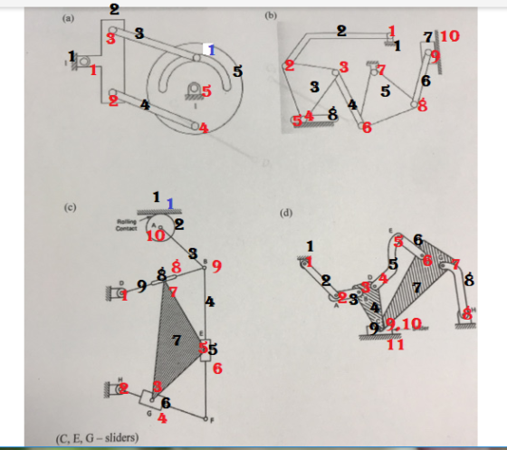
a:- No. of links L = 5 no. of binary joints= 5 (1,2,3,4,5) no. of lower pairs j = 5 no. of higher pair h= 1
DOF = 3(L-1) - 2j - h DOF = 3(5-1) - 2x5 - 1 DOF = 1
b:-
No. of links L = 8 no. of binary joints= 8 (1,2,3,4,6,7,8,9) no. of lower pairs j = 10 no. of higher pair h= 0
DOF = 3(L-1) - 2j - h DOF = 3(8-1) - 2x10 DOF=1
c:- NOTE:- in above diagram link HF is not considered plz consider it so no. of link become 10
No. of links L = 10 no. of binary joints= 8 (1,2,3,5,7,9,10,F) no. of lower pairs j = 11 no. of higher pair h= 1
DOF = 3(L-1) - 2j - h DOF= 3(10-1) - 2x11 -1 DOF= 4
d:-
No. of links L = 9 no. of binary joints= 8 (1,2,3,4,5,6,7,8)
at link 9 there is a ternary joint that is equal to two binary joints(9,10)
no. of lower pairs j = 11 no. of higher pair h= 0
DOF = 3(L-1) - 2j - h DOF = 3(9-1) - 2x11 -0 DOF = 2
Add Answer to:
1. (40%) For each mechanism shown below, determine the number of links, number of joints, and...
Problem 1 (70) For each mechanism shown: . Give number of links, elements, joints and DOF...
 Problem 1 (70) For each mechanism shown: . Give number of links, elements, joints and DOF 2. Give link type: binary, ternary, n-element etc. (b) (a) 4 +C3 3 Rolling Contact 6 2 2 (d)
2. DEGREES of FREEDOM. Calculate the number of degrees of freedom for the mechanism shown. Clearly...
 2. DEGREES of FREEDOM. Calculate the number of degrees of freedom for the mechanism shown. Clearly label all links and joints. OTH Slider
4) Determine the mobility of each planar linkage shown below, specify the number of joints and...
 4) Determine the mobility of each planar linkage shown below, specify the number of joints and members. 5) Determine the mobility of each of the planar linkages shown below. Specify the number of links and members. 6) Determine the mobility associated with the mechanism below. The round part rolls without slipping on the pieces in contact with it 7) If position information is available for all points in the planar linkage shown below, can all the velocities be determined uniquely...
For each of the mechanisms, draw the kinematic diagram, specify the number of links and joints, a...
 For each of the mechanisms, draw the kinematic diagram, specify the number of links and joints, and calculate the mobility (degrees of freedom) Microwave Linear actuator oven carrier
For each of the mechanisms, draw the kinematic diagram, specify the number of links and joints, and calculate the mobility (degrees of freedom) Microwave Linear actuator oven carrier
For each of the mechanisms, draw the kinematic diagram, specify the number of links and joints, and calculate the mobility (degrees of freedom) Microwave Linear actuator oven carrier
1) For the two mechanisms below identify the links and the oints. Determine the number of...
 1) For the two mechanisms below identify the links and the oints. Determine the number of degrees of freedom of each mechanism and explain if their motion is determinate for the inputs shown. Assume both slip and no slip between the cam and the roller. Load Hydraulic cylinder (input) roller Fork input
8) Determine the mobility for each of the mechanism shown. Specify the number of joints and...
 8) Determine the mobility for each of the mechanism shown. Specify the number of joints and members. Cam Contact Pin in Pin in Pin in 9) Determine which (if either) of the following linkages can be driven by a constant-velocity motor 4.2 2.0 5.0" 2.0" 2.6 4.0 5.2" 2.7" 10) Determine the mobility associated with the mechanism below. The figure is a schematic of the entire linkage for a large power shovel used in strip mining. It can cut into...
Ints) For the following mechanism: a. Determine the number of links in the mechanism b. Determine...
 ints) For the following mechanism: a. Determine the number of links in the mechanism b. Determine the total joint order in the mechanism c. Determine the number of loops required for this mechanism d. Determine the mobility of this mechanism e. Draw an appropriate vector loop for this mechanism f. Write the vector loop equation(s) in vector form. g. Write the scalar components of the vector loop position equations. h. Determine any geometric constraint equations. i. Determine the scalar known(s)....
P4.3: The crank-slider offset mechanism shown in Figure P4.3 has the link lengths: Las - 4",...
 P4.3: The crank-slider offset mechanism shown in Figure P4.3 has the link lengths: Las - 4", Lap = 24", Loc=0.19". The location of COM is as follows: LAG = 2.330"; LEG2 = 12"; LDG: = 0". In the initial position (home position), 0.19" Tact HO CO 1" o 28 the crank AB makes 0° with the horizontal, where the coordinates of contact point Care (28", 1"). The crank 1 rotates counterclockwise with the angu- lar displacement 0 = 2t (rad),...
Given: A mechanism is made up of links AB and BD, with point A being pinned...
 Given: A mechanism is made up of links AB and BD, with point A being pinned to ground and point B being a pin joint connecting links AB and BD. A slider is connected to BD at pin D with the slider being constrained to move on a circular path with a radius of R. At the position shown below, link AB is vertical, link BD is horizontal and D is directly above point 0. At this position, D is...
03 For the static equilibrium of the quick return mechanism shown in Fig (a), determine the input torque T2: to be a...
 03 For the static equilibrium of the quick return mechanism shown in Fig (a), determine the input torque T2: to be applied on link AB Tor a force of 300N on the slider D. use scale 1: 1 for The dimensions of the various links 300 N 400 105 400
03 For the static equilibrium of the quick return mechanism shown in Fig (a), determine the input torque T2: to be applied on link AB Tor a force of 300N...
03 For the static equilibrium of the quick return mechanism shown in Fig (a), determine the input torque T2: to be applied on link AB Tor a force of 300N on the slider D. use scale 1: 1 for The dimensions of the various links 300 N 400 105 400
03 For the static equilibrium of the quick return mechanism shown in Fig (a), determine the input torque T2: to be applied on link AB Tor a force of 300N...
 Problem 1 (70) For each mechanism shown: . Give number of links, elements, joints and DOF 2. Give link type: binary, ternary, n-element etc. (b) (a) 4 +C3 3 Rolling Contact 6 2 2 (d)
 2. DEGREES of FREEDOM. Calculate the number of degrees of freedom for the mechanism shown. Clearly label all links and joints. OTH Slider
 4) Determine the mobility of each planar linkage shown below, specify the number of joints and members. 5) Determine the mobility of each of the planar linkages shown below. Specify the number of links and members. 6) Determine the mobility associated with the mechanism below. The round part rolls without slipping on the pieces in contact with it 7) If position information is available for all points in the planar linkage shown below, can all the velocities be determined uniquely...
 For each of the mechanisms, draw the kinematic diagram, specify the number of links and joints, and calculate the mobility (degrees of freedom) Microwave Linear actuator oven carrier
For each of the mechanisms, draw the kinematic diagram, specify the number of links and joints, and calculate the mobility (degrees of freedom) Microwave Linear actuator oven carrier
For each of the mechanisms, draw the kinematic diagram, specify the number of links and joints, and calculate the mobility (degrees of freedom) Microwave Linear actuator oven carrier
 1) For the two mechanisms below identify the links and the oints. Determine the number of degrees of freedom of each mechanism and explain if their motion is determinate for the inputs shown. Assume both slip and no slip between the cam and the roller. Load Hydraulic cylinder (input) roller Fork input
 8) Determine the mobility for each of the mechanism shown. Specify the number of joints and members. Cam Contact Pin in Pin in Pin in 9) Determine which (if either) of the following linkages can be driven by a constant-velocity motor 4.2 2.0 5.0" 2.0" 2.6 4.0 5.2" 2.7" 10) Determine the mobility associated with the mechanism below. The figure is a schematic of the entire linkage for a large power shovel used in strip mining. It can cut into...
 ints) For the following mechanism: a. Determine the number of links in the mechanism b. Determine the total joint order in the mechanism c. Determine the number of loops required for this mechanism d. Determine the mobility of this mechanism e. Draw an appropriate vector loop for this mechanism f. Write the vector loop equation(s) in vector form. g. Write the scalar components of the vector loop position equations. h. Determine any geometric constraint equations. i. Determine the scalar known(s)....
 P4.3: The crank-slider offset mechanism shown in Figure P4.3 has the link lengths: Las - 4", Lap = 24", Loc=0.19". The location of COM is as follows: LAG = 2.330"; LEG2 = 12"; LDG: = 0". In the initial position (home position), 0.19" Tact HO CO 1" o 28 the crank AB makes 0° with the horizontal, where the coordinates of contact point Care (28", 1"). The crank 1 rotates counterclockwise with the angu- lar displacement 0 = 2t (rad),...
 Given: A mechanism is made up of links AB and BD, with point A being pinned to ground and point B being a pin joint connecting links AB and BD. A slider is connected to BD at pin D with the slider being constrained to move on a circular path with a radius of R. At the position shown below, link AB is vertical, link BD is horizontal and D is directly above point 0. At this position, D is...
 03 For the static equilibrium of the quick return mechanism shown in Fig (a), determine the input torque T2: to be applied on link AB Tor a force of 300N on the slider D. use scale 1: 1 for The dimensions of the various links 300 N 400 105 400
03 For the static equilibrium of the quick return mechanism shown in Fig (a), determine the input torque T2: to be applied on link AB Tor a force of 300N...
03 For the static equilibrium of the quick return mechanism shown in Fig (a), determine the input torque T2: to be applied on link AB Tor a force of 300N on the slider D. use scale 1: 1 for The dimensions of the various links 300 N 400 105 400
03 For the static equilibrium of the quick return mechanism shown in Fig (a), determine the input torque T2: to be applied on link AB Tor a force of 300N...
Most questions answered within 3 hours.
-
Why [M(CN)6] is not organometallic even it has metal
to carbon bond too
asked 1 minute ago -
mstar electric has a bond issue outstanding that has a 20 year
life, a $1,000 par...
asked 8 minutes ago -
This is a Business Writing Question:
Common Types of Faulty Sentence Logic:
A. Mixed constructions
B....
asked 9 minutes ago -
Skinner asserts that science, and the common view of science, has
been tarnished. Explain his evidence...
asked 12 minutes ago -
Question 3 (1 point)
Fill in the blank. Speed Car Rental company found that the tire...
asked 12 minutes ago -
An short-seller in Tesla is worried the latest management
earnings forecast is too aggressive and the...
asked 13 minutes ago -
A grocery store's receipts show that Sunday customer purchases
have a skewed distribution with a mean...
asked 18 minutes ago -
A 0.035 mol sample of a weak acid, HA, is dissolved in 437 mL of
water...
asked 30 minutes ago -
a sample of Ar gas has a volume of 6.30 L with an unknown
pressure. the...
asked 30 minutes ago -
The
serum cholesterol levels of a population of kids follow a normal
distribution with mean 155...
asked 50 minutes ago -
han discusses the racist practice of badlands, a bar
in the Castro
district of San Francisco,...
asked 1 hour ago -
A sample of final exam scores is normally distributed with a
mean equal to 25 and...
asked 1 hour ago