
Homework Answers

Add Answer to:
please show all steps
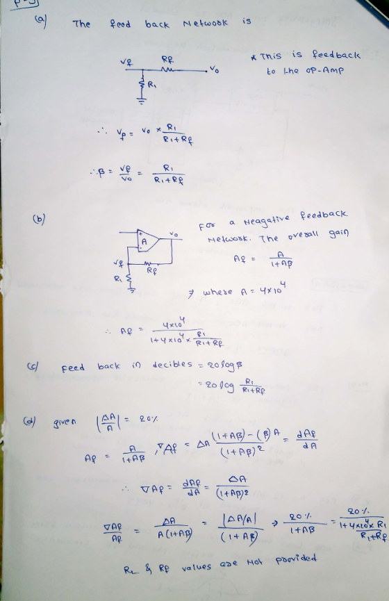
(5) 20pts) An op-amp configuration show below, please figure out the fp...
Please show all work and answer all part. #1. Consider the ideal op amp circuit below...
 Please show all work and answer all part.
#1. Consider the ideal op amp circuit below with R = 192, R, = 212, R2 = 312, I = 0.2A : a) Using circuit laws and properties of op-amps find voltage V, and currents in all resistors. b) Find the gain(s) of the amplifier circuit and explain what kind of gain it is. c) Find the input resistance(s) of the amplifier. d) Find the output resistance of the amplifier
Please show all work and answer all part.
#1. Consider the ideal op amp circuit below with R = 192, R, = 212, R2 = 312, I = 0.2A : a) Using circuit laws and properties of op-amps find voltage V, and currents in all resistors. b) Find the gain(s) of the amplifier circuit and explain what kind of gain it is. c) Find the input resistance(s) of the amplifier. d) Find the output resistance of the amplifier
Part A only please Part A - Analysis of an op-amp circuit using a realistic circuit...
 Part A only please
Part A - Analysis of an op-amp circuit using a realistic circuit model Learning Goal For an ideal op-amp, we assume that the current flowing into the More realistically, calculatei in the circuit given when R1 9.6 k, R2 -4.2 kQ R3-95 ko. V,-2920 μν , and Voe-15 V . Assume that the op-amp can be modeled with an input resistance of Ri-6.00 M, an output resistance of Ro- 9.5 kS2, and an open-loop gain of...
Part A only please
Part A - Analysis of an op-amp circuit using a realistic circuit model Learning Goal For an ideal op-amp, we assume that the current flowing into the More realistically, calculatei in the circuit given when R1 9.6 k, R2 -4.2 kQ R3-95 ko. V,-2920 μν , and Voe-15 V . Assume that the op-amp can be modeled with an input resistance of Ri-6.00 M, an output resistance of Ro- 9.5 kS2, and an open-loop gain of...
T5.1 Can someone please walk me through this? 1. An op-amp circuit is shown below. It...
 T5.1
Can someone please walk me through this?
1. An op-amp circuit is shown below. It has open-loop parameters rjn = 1MQ, rout = 1002, AQ 10 and is connected as a non-inverting amplifier with Ri=10k2 and R2 50k What kind of feedback topology does this represent? Find the closed-loop parameters Rin, Rout, and Af + rin rout Vout Vin Vs AoVin R2 W R1 Answer: Series-Shunt Feedback R R1//R2 8.3kQ R22 = Ri + R2 = 60k2 AR2lin =99x103...
T5.1
Can someone please walk me through this?
1. An op-amp circuit is shown below. It has open-loop parameters rjn = 1MQ, rout = 1002, AQ 10 and is connected as a non-inverting amplifier with Ri=10k2 and R2 50k What kind of feedback topology does this represent? Find the closed-loop parameters Rin, Rout, and Af + rin rout Vout Vin Vs AoVin R2 W R1 Answer: Series-Shunt Feedback R R1//R2 8.3kQ R22 = Ri + R2 = 60k2 AR2lin =99x103...
Please solve the Worksheet +V Figure 5. Op amp negative feedback circuit. Node Signal Figure 6....
 Please solve the Worksheet
+V Figure 5. Op amp negative feedback circuit. Node Signal Figure 6. Current Relationships R, Node n (0 Vw 3.3.Discovery Exercise: In your worksheet, use the information above to develop a formula for the gain, which you will use in the exereises below. Pre-Work: Prior to lab, review exercise and complete Worksheet #7. Experimental Procedure: 5.1.Negative Feedback Amplifier: In t 4. 5. he exercises be low, record the measured value of the selected resistors and enter...
Please solve the Worksheet
+V Figure 5. Op amp negative feedback circuit. Node Signal Figure 6. Current Relationships R, Node n (0 Vw 3.3.Discovery Exercise: In your worksheet, use the information above to develop a formula for the gain, which you will use in the exereises below. Pre-Work: Prior to lab, review exercise and complete Worksheet #7. Experimental Procedure: 5.1.Negative Feedback Amplifier: In t 4. 5. he exercises be low, record the measured value of the selected resistors and enter...
Please show all steps 1. Find the output resistance of the folded cascode shown below, in...
 Please show all steps
1. Find the output resistance of the folded cascode shown below, in which M3 operates as a current source. out NN.2 MI M3 bias3 2. The differential pair shown below has VDD-Vss-12 V, Rss-220 kΩ and RD-330 kQ. k,,WL-400 μ A/Vand V, = 1 V. Find the bias point for the transistors, the differential- mode gain and the common-mode gain (both for differential output) , v. RD DI D2 V.
Please show all steps
1. Find the output resistance of the folded cascode shown below, in which M3 operates as a current source. out NN.2 MI M3 bias3 2. The differential pair shown below has VDD-Vss-12 V, Rss-220 kΩ and RD-330 kQ. k,,WL-400 μ A/Vand V, = 1 V. Find the bias point for the transistors, the differential- mode gain and the common-mode gain (both for differential output) , v. RD DI D2 V.
please show steps, and solve asap BEE 433 Electronic Circuit Design Problem Set #1 Due date:...
 please show steps, and solve asap
BEE 433 Electronic Circuit Design Problem Set #1 Due date: Answer the following problems and Circle the answers. 1.1 (Fig. 1.1 from the textbook) In the voltage amplifier circuit of Fig. 1.1, let vs = 100 mV, Rs = 100 k 52, Vi = 75 mV, RL = 10 S2, and vo = 2 V. If connecting a 30-S2 resistance in parallel with RL drops vo to 1.8 V, find Ri, A., and R....
please show steps, and solve asap
BEE 433 Electronic Circuit Design Problem Set #1 Due date: Answer the following problems and Circle the answers. 1.1 (Fig. 1.1 from the textbook) In the voltage amplifier circuit of Fig. 1.1, let vs = 100 mV, Rs = 100 k 52, Vi = 75 mV, RL = 10 S2, and vo = 2 V. If connecting a 30-S2 resistance in parallel with RL drops vo to 1.8 V, find Ri, A., and R....
Please show all the steps. Thank you! 3. Spence, problem 3.6 For the cireuit shown below,...
 Please show all the steps. Thank you!
3. Spence, problem 3.6 For the cireuit shown below, find the valaes of voltages Vi and Va 31Ω iov 4. Spence, problem 3.11, modified In the cireuit shown below, cireuit element "X" requires 4V at 1.5mA and circuit element Y operates at 2V and 1mA. The two elements are to be operated from a single 9V battery as shown (a) Design the cireuit;ie, specfy appropriste values for Ri and Ra (b) Could appeopriate...
Please show all the steps. Thank you!
3. Spence, problem 3.6 For the cireuit shown below, find the valaes of voltages Vi and Va 31Ω iov 4. Spence, problem 3.11, modified In the cireuit shown below, cireuit element "X" requires 4V at 1.5mA and circuit element Y operates at 2V and 1mA. The two elements are to be operated from a single 9V battery as shown (a) Design the cireuit;ie, specfy appropriste values for Ri and Ra (b) Could appeopriate...
Please help with 5 and 6 AND SHOW UNITS 1. What is the resistance of a...
 Please help with 5 and 6
AND SHOW UNITS 1. What is the resistance of a thin tube iled with saline solution that is 2 cm in length and has a cross sectional area of 1 x 10 m2? Assume the resistivity of salline solution to be 0.1 Qm How 2. much charge is moved over a period of 10 s for a circuit that has a current of 0.2 amperes? 3. A). Wha ch t is the electrical force...
Please help with 5 and 6
AND SHOW UNITS 1. What is the resistance of a thin tube iled with saline solution that is 2 cm in length and has a cross sectional area of 1 x 10 m2? Assume the resistivity of salline solution to be 0.1 Qm How 2. much charge is moved over a period of 10 s for a circuit that has a current of 0.2 amperes? 3. A). Wha ch t is the electrical force...
I am currently trying to figure out the experiment below. Please complete Table 1 with an...
 I am currently trying to figure out the experiment below. Please
complete Table 1 with an explanation, I appreciate it thank
you! Promise to give thumbs up!
Introduction The phase differences between the output voltage, the voltage across the inductor, the voltage across the capacitor, and the voltage across the resistor will be examined at resonant frequency. The voltage and phase relationship will also be examined for frequencies above and below resonance. Theory An inductor, a capacitor, and a resistor are...
I am currently trying to figure out the experiment below. Please
complete Table 1 with an explanation, I appreciate it thank
you! Promise to give thumbs up!
Introduction The phase differences between the output voltage, the voltage across the inductor, the voltage across the capacitor, and the voltage across the resistor will be examined at resonant frequency. The voltage and phase relationship will also be examined for frequencies above and below resonance. Theory An inductor, a capacitor, and a resistor are...
 Please show all work and answer all part.
#1. Consider the ideal op amp circuit below with R = 192, R, = 212, R2 = 312, I = 0.2A : a) Using circuit laws and properties of op-amps find voltage V, and currents in all resistors. b) Find the gain(s) of the amplifier circuit and explain what kind of gain it is. c) Find the input resistance(s) of the amplifier. d) Find the output resistance of the amplifier
Please show all work and answer all part.
#1. Consider the ideal op amp circuit below with R = 192, R, = 212, R2 = 312, I = 0.2A : a) Using circuit laws and properties of op-amps find voltage V, and currents in all resistors. b) Find the gain(s) of the amplifier circuit and explain what kind of gain it is. c) Find the input resistance(s) of the amplifier. d) Find the output resistance of the amplifier
 Part A only please
Part A - Analysis of an op-amp circuit using a realistic circuit model Learning Goal For an ideal op-amp, we assume that the current flowing into the More realistically, calculatei in the circuit given when R1 9.6 k, R2 -4.2 kQ R3-95 ko. V,-2920 μν , and Voe-15 V . Assume that the op-amp can be modeled with an input resistance of Ri-6.00 M, an output resistance of Ro- 9.5 kS2, and an open-loop gain of...
Part A only please
Part A - Analysis of an op-amp circuit using a realistic circuit model Learning Goal For an ideal op-amp, we assume that the current flowing into the More realistically, calculatei in the circuit given when R1 9.6 k, R2 -4.2 kQ R3-95 ko. V,-2920 μν , and Voe-15 V . Assume that the op-amp can be modeled with an input resistance of Ri-6.00 M, an output resistance of Ro- 9.5 kS2, and an open-loop gain of...
 T5.1
Can someone please walk me through this?
1. An op-amp circuit is shown below. It has open-loop parameters rjn = 1MQ, rout = 1002, AQ 10 and is connected as a non-inverting amplifier with Ri=10k2 and R2 50k What kind of feedback topology does this represent? Find the closed-loop parameters Rin, Rout, and Af + rin rout Vout Vin Vs AoVin R2 W R1 Answer: Series-Shunt Feedback R R1//R2 8.3kQ R22 = Ri + R2 = 60k2 AR2lin =99x103...
T5.1
Can someone please walk me through this?
1. An op-amp circuit is shown below. It has open-loop parameters rjn = 1MQ, rout = 1002, AQ 10 and is connected as a non-inverting amplifier with Ri=10k2 and R2 50k What kind of feedback topology does this represent? Find the closed-loop parameters Rin, Rout, and Af + rin rout Vout Vin Vs AoVin R2 W R1 Answer: Series-Shunt Feedback R R1//R2 8.3kQ R22 = Ri + R2 = 60k2 AR2lin =99x103...
 Please solve the Worksheet
+V Figure 5. Op amp negative feedback circuit. Node Signal Figure 6. Current Relationships R, Node n (0 Vw 3.3.Discovery Exercise: In your worksheet, use the information above to develop a formula for the gain, which you will use in the exereises below. Pre-Work: Prior to lab, review exercise and complete Worksheet #7. Experimental Procedure: 5.1.Negative Feedback Amplifier: In t 4. 5. he exercises be low, record the measured value of the selected resistors and enter...
Please solve the Worksheet
+V Figure 5. Op amp negative feedback circuit. Node Signal Figure 6. Current Relationships R, Node n (0 Vw 3.3.Discovery Exercise: In your worksheet, use the information above to develop a formula for the gain, which you will use in the exereises below. Pre-Work: Prior to lab, review exercise and complete Worksheet #7. Experimental Procedure: 5.1.Negative Feedback Amplifier: In t 4. 5. he exercises be low, record the measured value of the selected resistors and enter...
 Please show all steps
1. Find the output resistance of the folded cascode shown below, in which M3 operates as a current source. out NN.2 MI M3 bias3 2. The differential pair shown below has VDD-Vss-12 V, Rss-220 kΩ and RD-330 kQ. k,,WL-400 μ A/Vand V, = 1 V. Find the bias point for the transistors, the differential- mode gain and the common-mode gain (both for differential output) , v. RD DI D2 V.
Please show all steps
1. Find the output resistance of the folded cascode shown below, in which M3 operates as a current source. out NN.2 MI M3 bias3 2. The differential pair shown below has VDD-Vss-12 V, Rss-220 kΩ and RD-330 kQ. k,,WL-400 μ A/Vand V, = 1 V. Find the bias point for the transistors, the differential- mode gain and the common-mode gain (both for differential output) , v. RD DI D2 V.
 please show steps, and solve asap
BEE 433 Electronic Circuit Design Problem Set #1 Due date: Answer the following problems and Circle the answers. 1.1 (Fig. 1.1 from the textbook) In the voltage amplifier circuit of Fig. 1.1, let vs = 100 mV, Rs = 100 k 52, Vi = 75 mV, RL = 10 S2, and vo = 2 V. If connecting a 30-S2 resistance in parallel with RL drops vo to 1.8 V, find Ri, A., and R....
please show steps, and solve asap
BEE 433 Electronic Circuit Design Problem Set #1 Due date: Answer the following problems and Circle the answers. 1.1 (Fig. 1.1 from the textbook) In the voltage amplifier circuit of Fig. 1.1, let vs = 100 mV, Rs = 100 k 52, Vi = 75 mV, RL = 10 S2, and vo = 2 V. If connecting a 30-S2 resistance in parallel with RL drops vo to 1.8 V, find Ri, A., and R....
 Please show all the steps. Thank you!
3. Spence, problem 3.6 For the cireuit shown below, find the valaes of voltages Vi and Va 31Ω iov 4. Spence, problem 3.11, modified In the cireuit shown below, cireuit element "X" requires 4V at 1.5mA and circuit element Y operates at 2V and 1mA. The two elements are to be operated from a single 9V battery as shown (a) Design the cireuit;ie, specfy appropriste values for Ri and Ra (b) Could appeopriate...
Please show all the steps. Thank you!
3. Spence, problem 3.6 For the cireuit shown below, find the valaes of voltages Vi and Va 31Ω iov 4. Spence, problem 3.11, modified In the cireuit shown below, cireuit element "X" requires 4V at 1.5mA and circuit element Y operates at 2V and 1mA. The two elements are to be operated from a single 9V battery as shown (a) Design the cireuit;ie, specfy appropriste values for Ri and Ra (b) Could appeopriate...
 Please help with 5 and 6
AND SHOW UNITS 1. What is the resistance of a thin tube iled with saline solution that is 2 cm in length and has a cross sectional area of 1 x 10 m2? Assume the resistivity of salline solution to be 0.1 Qm How 2. much charge is moved over a period of 10 s for a circuit that has a current of 0.2 amperes? 3. A). Wha ch t is the electrical force...
Please help with 5 and 6
AND SHOW UNITS 1. What is the resistance of a thin tube iled with saline solution that is 2 cm in length and has a cross sectional area of 1 x 10 m2? Assume the resistivity of salline solution to be 0.1 Qm How 2. much charge is moved over a period of 10 s for a circuit that has a current of 0.2 amperes? 3. A). Wha ch t is the electrical force...
 I am currently trying to figure out the experiment below. Please
complete Table 1 with an explanation, I appreciate it thank
you! Promise to give thumbs up!
Introduction The phase differences between the output voltage, the voltage across the inductor, the voltage across the capacitor, and the voltage across the resistor will be examined at resonant frequency. The voltage and phase relationship will also be examined for frequencies above and below resonance. Theory An inductor, a capacitor, and a resistor are...
I am currently trying to figure out the experiment below. Please
complete Table 1 with an explanation, I appreciate it thank
you! Promise to give thumbs up!
Introduction The phase differences between the output voltage, the voltage across the inductor, the voltage across the capacitor, and the voltage across the resistor will be examined at resonant frequency. The voltage and phase relationship will also be examined for frequencies above and below resonance. Theory An inductor, a capacitor, and a resistor are...
Most questions answered within 3 hours.
-
A sock stuck to the side of a clothes-dryer barrel has a
centripetal acceleration of 24...
asked 2 minutes ago -
A perfect gas undergoes an isentropic process such that its
volume doubles. If the ratio of...
asked 22 minutes ago -
list the elements in groups 3A to 6A in the same order as in the
periodic...
asked 31 minutes ago -
Estimating effect size. Peng and Chen (2014)
evaluated effect size estimates for various tests. In their...
asked 41 minutes ago -
Write a script in MySQL that creates and calls a stored
procedure name test. This procedure...
asked 41 minutes ago -
If we test the following: H0: μ = 17
vs. H1: μ ≠ 17 and the...
asked 52 minutes ago -
in the past year TVG had revenues of 3 million, cost
of goods sold of $25...
asked 57 minutes ago -
4) In a polypeptide, which bond cannot rotate because of its
partial double bond character?
The...
asked 1 hour ago -
Assume that in the short run L = 1,000 and K = 100. 1. What is...
asked 1 hour ago -
At a given temperature, 2.06 atm of H2 and 3.7 atm of Br2 are
mixed and...
asked 1 hour ago -
Sodium reacts with Hydrochloric acid to form sodium chloride and
hydrogen gas. 2Na(s)+ 2 HCl(aq)-> 2...
asked 1 hour ago -
The following circuits (1 & 2) are combined to form a
series-parallel circuit and resulting circuit...
asked 1 hour ago