
Homework Answers

Add Answer to:
For the circuit below, 5. Find the output voltage (%) in terms of its inputs (v1...
Design an opamp circuit which will average inputs V1 & V2 with V0 = (V1 V2)/2.
Design an opamp circuit which will average inputs V1 & V2 with V0 = (V1 V2)/2.
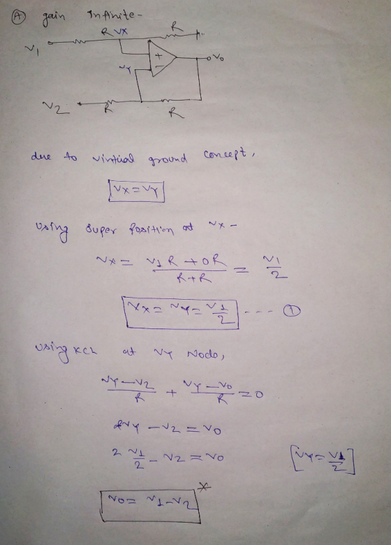
5. Assume that the Op-Amp in the adjoining circuit is ideal, and find the output voltage...
 5. Assume that the Op-Amp in the adjoining circuit is ideal, and find the output voltage V. in terms of the two input voltages V1 and V2 of the circuit. Ideal D2RE bi
Design the below operational amplifier circuit having one output, Vout, and two inputs, V1 and V2....
 Design the below operational amplifier circuit having one output, Vout, and two inputs, V1 and V2. The output must be related to the inputs by Vout = 2 V1 - 9 V2 26 km 180 kn 180 kn Rik - R2 kn Determine the value of R1 and Rz. R2 = ko R2 =
1. Find the expression for the output voltage Vou for the circuit shown below in terms...
 1. Find the expression for the output voltage Vou for the circuit shown below in terms of the resistors Ri, R, R and Rs and the input voltages Vi. V2 and V Calculate Vout when R.-R: = R.-1? and R.-10kfand V, = 4nnV, V,-5mV and V,-6m1V. N3. 2. Find the expression for the output voltage in the circuit shown below and calculate the output voltage Vou where R-R-2.2 k2 and R R-10kQ. V-4 V and V the output voltage when...
Find the output voltage Vo as an expression in terms of the input sources Vi, v2,...
 Find the output voltage Vo as an expression in terms of the input sources Vi, v2, v3, and the resistance R in the following op-amp circuit. 3. Ri Vy R: 4. In the following two stage op-amp circuit, find the output voltage Vo as an expression in terms of the input voltages v1, v2 and resistor values R1, R2, R3, and R4. R2 R ウー+
In the circuit below, the input voltage is Vin-Vinegakcos(wt), R-20 ΚΩandC15nFw l. in al Show that the output voltage is VotVcos (wt-), where V-V n peak/V1 + (RC) b) Show that this result justifies c...
 In the circuit below, the input voltage is Vin-Vinegakcos(wt), R-20 ΚΩandC15nFw l. in al Show that the output voltage is VotVcos (wt-), where V-V n peak/V1 + (RC) b) Show that this result justifies calling this circuit a high-pass filter+ c) Find an expression for the phase constant δ in terms of R,C and d) At what frequency is Vi (1/V2) Vin peak? That particular frequency is known as the 3dB frequency, or f3dB, of the circuit
In the circuit...
In the circuit below, the input voltage is Vin-Vinegakcos(wt), R-20 ΚΩandC15nFw l. in al Show that the output voltage is VotVcos (wt-), where V-V n peak/V1 + (RC) b) Show that this result justifies calling this circuit a high-pass filter+ c) Find an expression for the phase constant δ in terms of R,C and d) At what frequency is Vi (1/V2) Vin peak? That particular frequency is known as the 3dB frequency, or f3dB, of the circuit
In the circuit...
Problem 5.3-1 5 Ohms 20 Ohms o20 Ohms 2 The inputs to this circuit are the...
 Problem 5.3-1 5 Ohms 20 Ohms o20 Ohms 2 The inputs to this circuit are the voltage source voltages v1 and v2. The output of the circuit is the voltage vo The output is related to the inputs by where a and b are constants. Determine the values of a and b with units of mV/V. mV/V and b mV/V.
For the Op Amp circuit shown, if the inputs v1 = 5 volts, and v2 = 3 volts
 For the Op Amp circuit shown, if the inputs v1 = 5 volts, and v2 = 3 volts, and resistances R1 = R2 =10 KΩ and RF = 5kΩ , then the output out will be _______ volts. This circuit is called a _______ OP Amp circuit. The name indicates the application of the circuit. The Op Amp provides _______ output impedance.
b. Determine the symbolic expression for Vo2/V2 (Vo2: output voltage contributed by V2 when V1 =...
 b. Determine the symbolic expression for Vo2/V2 (Vo2: output
voltage contributed by V2 when V1 = 0).
c Determine the symbolic expression for Vo in terms of V1 and V2
using superposition.
d. This circuit is (circle two):
Non-inverting amp / Inverting amp / subtractor / adder
R1 R3 (4) (22%) Consider the op-amp circuit shown to the right. Assume the op-amp is ideal and operating in the linear range. Answer the following questions. M3 MV + (a) (7%) Determine...
b. Determine the symbolic expression for Vo2/V2 (Vo2: output
voltage contributed by V2 when V1 = 0).
c Determine the symbolic expression for Vo in terms of V1 and V2
using superposition.
d. This circuit is (circle two):
Non-inverting amp / Inverting amp / subtractor / adder
R1 R3 (4) (22%) Consider the op-amp circuit shown to the right. Assume the op-amp is ideal and operating in the linear range. Answer the following questions. M3 MV + (a) (7%) Determine...
Consider the following RLC circuit, v1 and v2 are the two inputs and v0 is the...
 Consider the following RLC circuit, v1 and v2 are the two inputs
and v0 is the output.
(a) Obtain the state-space representation for the system if the
state variables are defined as vc and iL.
(b) Draw a signal flow graph based on the state-space model
obtained in (a).
(c) The output can be derived as V0(s) = G1(s)V1(s) +
G2(s)V2(s). Use the state-space model obtained in (a) to find the
transfer fnctions G1(s) and G2(s).
2 0
Consider the following RLC circuit, v1 and v2 are the two inputs
and v0 is the output.
(a) Obtain the state-space representation for the system if the
state variables are defined as vc and iL.
(b) Draw a signal flow graph based on the state-space model
obtained in (a).
(c) The output can be derived as V0(s) = G1(s)V1(s) +
G2(s)V2(s). Use the state-space model obtained in (a) to find the
transfer fnctions G1(s) and G2(s).
2 0
 5. Assume that the Op-Amp in the adjoining circuit is ideal, and find the output voltage V. in terms of the two input voltages V1 and V2 of the circuit. Ideal D2RE bi
 Design the below operational amplifier circuit having one output, Vout, and two inputs, V1 and V2. The output must be related to the inputs by Vout = 2 V1 - 9 V2 26 km 180 kn 180 kn Rik - R2 kn Determine the value of R1 and Rz. R2 = ko R2 =
 1. Find the expression for the output voltage Vou for the circuit shown below in terms of the resistors Ri, R, R and Rs and the input voltages Vi. V2 and V Calculate Vout when R.-R: = R.-1? and R.-10kfand V, = 4nnV, V,-5mV and V,-6m1V. N3. 2. Find the expression for the output voltage in the circuit shown below and calculate the output voltage Vou where R-R-2.2 k2 and R R-10kQ. V-4 V and V the output voltage when...
 Find the output voltage Vo as an expression in terms of the input sources Vi, v2, v3, and the resistance R in the following op-amp circuit. 3. Ri Vy R: 4. In the following two stage op-amp circuit, find the output voltage Vo as an expression in terms of the input voltages v1, v2 and resistor values R1, R2, R3, and R4. R2 R ウー+
 In the circuit below, the input voltage is Vin-Vinegakcos(wt), R-20 ΚΩandC15nFw l. in al Show that the output voltage is VotVcos (wt-), where V-V n peak/V1 + (RC) b) Show that this result justifies calling this circuit a high-pass filter+ c) Find an expression for the phase constant δ in terms of R,C and d) At what frequency is Vi (1/V2) Vin peak? That particular frequency is known as the 3dB frequency, or f3dB, of the circuit
In the circuit...
In the circuit below, the input voltage is Vin-Vinegakcos(wt), R-20 ΚΩandC15nFw l. in al Show that the output voltage is VotVcos (wt-), where V-V n peak/V1 + (RC) b) Show that this result justifies calling this circuit a high-pass filter+ c) Find an expression for the phase constant δ in terms of R,C and d) At what frequency is Vi (1/V2) Vin peak? That particular frequency is known as the 3dB frequency, or f3dB, of the circuit
In the circuit...
 Problem 5.3-1 5 Ohms 20 Ohms o20 Ohms 2 The inputs to this circuit are the voltage source voltages v1 and v2. The output of the circuit is the voltage vo The output is related to the inputs by where a and b are constants. Determine the values of a and b with units of mV/V. mV/V and b mV/V.
 b. Determine the symbolic expression for Vo2/V2 (Vo2: output
voltage contributed by V2 when V1 = 0).
c Determine the symbolic expression for Vo in terms of V1 and V2
using superposition.
d. This circuit is (circle two):
Non-inverting amp / Inverting amp / subtractor / adder
R1 R3 (4) (22%) Consider the op-amp circuit shown to the right. Assume the op-amp is ideal and operating in the linear range. Answer the following questions. M3 MV + (a) (7%) Determine...
b. Determine the symbolic expression for Vo2/V2 (Vo2: output
voltage contributed by V2 when V1 = 0).
c Determine the symbolic expression for Vo in terms of V1 and V2
using superposition.
d. This circuit is (circle two):
Non-inverting amp / Inverting amp / subtractor / adder
R1 R3 (4) (22%) Consider the op-amp circuit shown to the right. Assume the op-amp is ideal and operating in the linear range. Answer the following questions. M3 MV + (a) (7%) Determine...
 Consider the following RLC circuit, v1 and v2 are the two inputs
and v0 is the output.
(a) Obtain the state-space representation for the system if the
state variables are defined as vc and iL.
(b) Draw a signal flow graph based on the state-space model
obtained in (a).
(c) The output can be derived as V0(s) = G1(s)V1(s) +
G2(s)V2(s). Use the state-space model obtained in (a) to find the
transfer fnctions G1(s) and G2(s).
2 0
Consider the following RLC circuit, v1 and v2 are the two inputs
and v0 is the output.
(a) Obtain the state-space representation for the system if the
state variables are defined as vc and iL.
(b) Draw a signal flow graph based on the state-space model
obtained in (a).
(c) The output can be derived as V0(s) = G1(s)V1(s) +
G2(s)V2(s). Use the state-space model obtained in (a) to find the
transfer fnctions G1(s) and G2(s).
2 0
Most questions answered within 3 hours.
-
You roll a fair 6-sided dice, let Y be the outcome of the dice
roll. Then...
asked 19 minutes ago -
If the value of the range is equal to zero, then this indicates
that:
A. there...
asked 39 minutes ago -
Based on Simms' (1994) articulation of psychological privacy to
promote development of self-identity, for example, do...
asked 2 minutes ago -
Use C programe to :
Develop an algorithm, flow chart and write a C program to...
asked 24 minutes ago -
Benzene has a vapor pressure of 75.0 Torr at 22.0 °C and an
enthalpy of evaporation...
asked 8 minutes ago -
How does a leadership philosophy shape service delivery in a
human services organization?
asked 17 minutes ago -
Which of the following statements about hormonal regulation of
glycogen synthesis and degradation are correct?
Multiple...
asked 22 minutes ago -
1. Describe all
necessary steps and conditions for execution of a java".
2. What
is maven...
asked 34 minutes ago -
What is the temperature of a 3.5L container with 1.502 mol
carbon dioxide at 10.76 atm?...
asked 29 minutes ago -
A dragster makes a pass down a track in exactly 7.03 seconds.
You do not know,...
asked 34 minutes ago -
What evidence can you provide to illustrate why
crowdsourcing is able to reduce system development costs?...
asked 38 minutes ago -
Hi, I was wondering if I could get some help on a java program
that I...
asked 45 minutes ago