Explain with the aid of a diagram why a Zener diode is not suitable to act...
Explain with the aid of a diagram why a Zener diode is not suitable to act as a stable reference voltage.
Homework Answers

Add Answer to:
Explain with the aid of a diagram why a Zener diode is not
suitable to act...
Design a circuit based on the canes zener diode that runs on a single 15V battery...
Design a circuit based on the canes zener diode that runs on a single 15V battery and provides a reference voltage of 7.5V. Draw the circuit showing all neccessary components and their values. -The canes zener diode has a maximum current rating of 200 mA and a zener voltage. please solve and explain
4. Design a clamp circuit to clamp the negative extreme of a periodic input waveform of 10 sin(100πt)V to −5 V. Use 1 diode, 1 Zener diode, 1 resistor, and 1 capacitor of suitable values. Provide foll...
4. Design a clamp circuit to clamp the negative extreme of a periodic input waveform of 10 sin(100πt)V to −5 V. Use 1 diode, 1 Zener diode, 1 resistor, and 1 capacitor of suitable values. Provide following minimum ratings of the selected components. (a) Diode - Maximum reverse voltage, peak forward current (b) Zener - Zener voltage, Zener current (c) Resistor - Resistance, power rating (d) capacitor - capacitance, Maximum voltage Assume a 0.6 V forward drop for all diodes...
Ctri Question 3 (20 Marks) Lab 1-Zener Circuits and Applications Theory: Zener diode is designed ...
 Ctri Question 3 (20 Marks) Lab 1-Zener Circuits and Applications Theory: Zener diode is designed to operate in reverse conduction. Zener breakdown occurs at a precisely defined voltage, allowing the diode to be used as a voltage reference or clipper. While Zener diodes are usually operated in reverse conduction, they may also be operated in cutoff and forward conduction. There are two different effects that are used in "Zener diodes". The only practical difference is that the two types have...
1. Draw the current-voltage characteristic of a Zener diode and show the forward and reverse biasing...
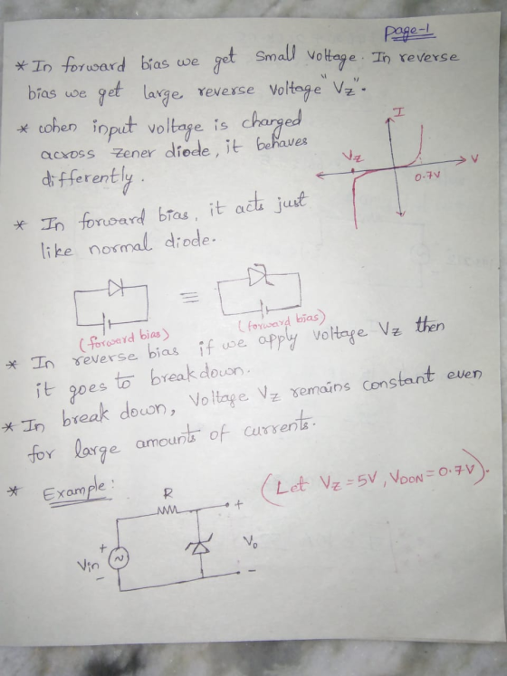
 1. Draw the current-voltage characteristic of a Zener diode and show the forward and reverse biasing areas. Mark the "Zener voltage" value on the graph. Explain how the voltage on the Zener diode will vary when it is biased with a voltage higher than the Zener voltage. 2. Explain the operating principle of a full-wave bridge rectifier by clarifying which diodes becomes active during the positive and negative cycles of the input signal.
Problem 3: (20 points) A zener-diode voltage regulator circuit is shown belkw zener diode has breakdown voltage Vz 8.0V and the zener resistance is nsumed to be 0 ohms. The power supply voltage V...
 Problem 3: (20 points) A zener-diode voltage regulator circuit is shown belkw zener diode has breakdown voltage Vz 8.0V and the zener resistance is nsumed to be 0 ohms. The power supply voltage Vps can vary between 10V and 14V and the lod resistance Ri can vary between 100 ohms and 1 kohm, 圧 1. Find a value of R such that the zener diode remains properly biased over the range of variation of Vps and RI (hint: the minimum...
that's all information it gives A zener-diode voltage regulator circuit is shown below. The tage V 8.0V and the zener resistance is assumed to Problem 3: (20 points) zener diode has breakdown...
 that's all information it gives
A zener-diode voltage regulator circuit is shown below. The tage V 8.0V and the zener resistance is assumed to Problem 3: (20 points) zener diode has breakdown vol be 0 ohms. The power supply voltage Vps can vary between resistance RL can vary between 100 ohms and 1 kohm. 10V and 14V and the load Ri PS 1. Find a value of Ri such that the zener diode remains properly biased over the range of...
that's all information it gives
A zener-diode voltage regulator circuit is shown below. The tage V 8.0V and the zener resistance is assumed to Problem 3: (20 points) zener diode has breakdown vol be 0 ohms. The power supply voltage Vps can vary between resistance RL can vary between 100 ohms and 1 kohm. 10V and 14V and the load Ri PS 1. Find a value of Ri such that the zener diode remains properly biased over the range of...
All used in the next circuit diodes are silicon. Zener of diode D2 the voltage is...
 All used in the next circuit diodes are silicon. Zener of diode
D2 the voltage is 8 V, the zener voltage of the D4 diode is 5.6 V
It is given as. Applied input voltage Vin = 20 sin (ωt) is
determined as V. Output of the circuit voltage changes according to
the applied voltage of Vin Analyze the circuit and draw it.
(Simplified of diode element model will be used.) (I can't analyze.
Please explain)
R + D D3...
All used in the next circuit diodes are silicon. Zener of diode
D2 the voltage is 8 V, the zener voltage of the D4 diode is 5.6 V
It is given as. Applied input voltage Vin = 20 sin (ωt) is
determined as V. Output of the circuit voltage changes according to
the applied voltage of Vin Analyze the circuit and draw it.
(Simplified of diode element model will be used.) (I can't analyze.
Please explain)
R + D D3...
In a Zener diode, the notation 5v6 means that the Zener voltage for breakdown is 5.6...
 In a Zener diode, the notation 5v6 means that the Zener voltage for breakdown is 5.6 volts(see for example, here: http://www.mouser.com/Search/Refine aspx?Keyword BZX55C-5V6). How many volts will be across the output of the circuit below (the voltage listed as "?") if the input power supply: safety resistor 0.7v 1V8本 6v2本 is 5 volts? - f it is 9 volts? If it is 12 volts? power supply Explain and/or show calculations:
With the aid of a suitable diagram explain how a thin film of refractive index n...
With the aid of a suitable diagram explain how a thin film of refractive index n can be used as an anti-reflective coating on a glass lens with refractive index ng.
Find the output voltage of this zener diode source. From the table in the data sheet...
 Find the output voltage of this zener diode source. From the table in the data sheet attached to the end of this file, find the zener voltage specifications for the 1N5231B part. What is the current flowing through the zener diode? Using Figs. 8 and 10 of the data sheet, estimate the output resistance of the source. Calculate the drop in the output voltage if a 20 k Ohm resistor is placed across the output.
 Ctri Question 3 (20 Marks) Lab 1-Zener Circuits and Applications Theory: Zener diode is designed to operate in reverse conduction. Zener breakdown occurs at a precisely defined voltage, allowing the diode to be used as a voltage reference or clipper. While Zener diodes are usually operated in reverse conduction, they may also be operated in cutoff and forward conduction. There are two different effects that are used in "Zener diodes". The only practical difference is that the two types have...
 1. Draw the current-voltage characteristic of a Zener diode and show the forward and reverse biasing areas. Mark the "Zener voltage" value on the graph. Explain how the voltage on the Zener diode will vary when it is biased with a voltage higher than the Zener voltage. 2. Explain the operating principle of a full-wave bridge rectifier by clarifying which diodes becomes active during the positive and negative cycles of the input signal.
 Problem 3: (20 points) A zener-diode voltage regulator circuit is shown belkw zener diode has breakdown voltage Vz 8.0V and the zener resistance is nsumed to be 0 ohms. The power supply voltage Vps can vary between 10V and 14V and the lod resistance Ri can vary between 100 ohms and 1 kohm, 圧 1. Find a value of R such that the zener diode remains properly biased over the range of variation of Vps and RI (hint: the minimum...
 that's all information it gives
A zener-diode voltage regulator circuit is shown below. The tage V 8.0V and the zener resistance is assumed to Problem 3: (20 points) zener diode has breakdown vol be 0 ohms. The power supply voltage Vps can vary between resistance RL can vary between 100 ohms and 1 kohm. 10V and 14V and the load Ri PS 1. Find a value of Ri such that the zener diode remains properly biased over the range of...
that's all information it gives
A zener-diode voltage regulator circuit is shown below. The tage V 8.0V and the zener resistance is assumed to Problem 3: (20 points) zener diode has breakdown vol be 0 ohms. The power supply voltage Vps can vary between resistance RL can vary between 100 ohms and 1 kohm. 10V and 14V and the load Ri PS 1. Find a value of Ri such that the zener diode remains properly biased over the range of...
 All used in the next circuit diodes are silicon. Zener of diode
D2 the voltage is 8 V, the zener voltage of the D4 diode is 5.6 V
It is given as. Applied input voltage Vin = 20 sin (ωt) is
determined as V. Output of the circuit voltage changes according to
the applied voltage of Vin Analyze the circuit and draw it.
(Simplified of diode element model will be used.) (I can't analyze.
Please explain)
R + D D3...
All used in the next circuit diodes are silicon. Zener of diode
D2 the voltage is 8 V, the zener voltage of the D4 diode is 5.6 V
It is given as. Applied input voltage Vin = 20 sin (ωt) is
determined as V. Output of the circuit voltage changes according to
the applied voltage of Vin Analyze the circuit and draw it.
(Simplified of diode element model will be used.) (I can't analyze.
Please explain)
R + D D3...
 In a Zener diode, the notation 5v6 means that the Zener voltage for breakdown is 5.6 volts(see for example, here: http://www.mouser.com/Search/Refine aspx?Keyword BZX55C-5V6). How many volts will be across the output of the circuit below (the voltage listed as "?") if the input power supply: safety resistor 0.7v 1V8本 6v2本 is 5 volts? - f it is 9 volts? If it is 12 volts? power supply Explain and/or show calculations:
 Find the output voltage of this zener diode source. From the table in the data sheet attached to the end of this file, find the zener voltage specifications for the 1N5231B part. What is the current flowing through the zener diode? Using Figs. 8 and 10 of the data sheet, estimate the output resistance of the source. Calculate the drop in the output voltage if a 20 k Ohm resistor is placed across the output.
Most questions answered within 3 hours.
-
A firm faces the following average revenue (demand) curve: P =
120 – 0.02Q
where Q...
asked 9 minutes ago -
A photographer wants to produce an image with a very narrow
depth of field so that...
asked 13 minutes ago -
Compare/contrast the anatomy of the snail, the clam, and the
squid based on features in a...
asked 23 minutes ago -
A pulse is sent traveling along a rope under a tension of 33 N
whose mass...
asked 26 minutes ago -
Mr. Appiah has GHS 200,000 for investment. In order to
diversify his risk Mr. Appiah is...
asked 33 minutes ago -
Programming project in Java:
You are allowed to use the following methods from the
Java API:...
asked 47 minutes ago -
The enthalpy change, ΔH, for a reaction at constant pressure is
defined as:
ΔH = ΔE...
asked 54 minutes ago -
What are the two main reasons for including covariates in ANOVA?
a. 1.) To increase within-group...
asked 55 minutes ago -
There are balls numbered 1, 2, 3, 4, 5, 6, 7 in a box, 2 balls...
asked 2 hours ago -
Based on the mutual fund NAVs below, how many shares will $600
buy you, if you...
asked 1 hour ago -
what effect on total protein concentration would you
expect to see during dehydration? explain your reasoning.
asked 2 hours ago -
You are the operations manager of a firm that uses the
continuous review inventory control system....
asked 5 hours ago