
Homework Answers


Add Answer to:
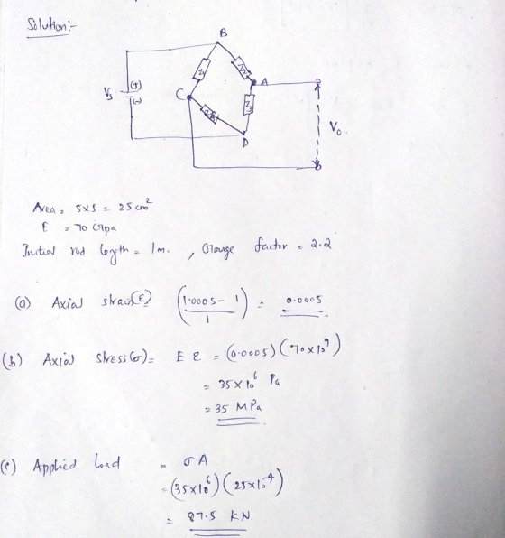
Problem #1 (35 pts.) A solid 5 cm by 5 cm square aluminum rod, with a...
3. A 2.8 cm x 5.0 cm rectangular rod is stretched from its initial length of 0.4000 m to a length of 0.4005 m. The Young’s modulus of the rod material is 95 GPa. Poisson’s ratio of the rod material is...
 3. A 2.8 cm x 5.0 cm rectangular rod is stretched from its
initial length of 0.4000 m to a length of 0.4005 m. The Young’s
modulus of the rod material is 95 GPa. Poisson’s ratio of the rod
material is 0.333.
A) Calculate the axial stress in units of MPa
B) Calculate the transverse strain in units of microstrain
C) A strain gauge with a strain gauge factor of 2.1 is glued to
the rod before it is stretched,...
3. A 2.8 cm x 5.0 cm rectangular rod is stretched from its
initial length of 0.4000 m to a length of 0.4005 m. The Young’s
modulus of the rod material is 95 GPa. Poisson’s ratio of the rod
material is 0.333.
A) Calculate the axial stress in units of MPa
B) Calculate the transverse strain in units of microstrain
C) A strain gauge with a strain gauge factor of 2.1 is glued to
the rod before it is stretched,...
A strain gauge that has a nominal resistance of 350 ? and a gauge factor of...
 A strain gauge that has a nominal resistance of 350 ? and a gauge factor of 1.8 is mounted in an equal-arm bridge, which is balanced at a zero applied strain condition. The gauge is mounted on a 11.8 1-cm aluminum rod, with E 70 GPa. The gauge senses axial strain. The bridge output is 1 mV for a bridge input of 5 V. What is the applied load, assuming the rod is in uniaxial tension?
As shown below (Fig.1), A strain gage with gage factor of 2.02 is mounted on the bottom of a beam...
 As shown below (Fig.1), A strain gage with gage factor of 2.02 is mounted on the bottom of a beam to measure the strain on the surface of the beam. The beam's Young's Modulus is 193 GPa. A wheatstone bridge circuit was constructed as sketched in Fig. 2. Al resistors including the gage itself is 1202. Supply voltage is 5.0 V DC. The bridge is initially balanced when there is no load (a). when a downward load is added, will...
P2: (40points) As shown below (Fig.1), A strain gage with gage factor of 2.02 is mounted on the b...
 P2: (40points) As shown below (Fig.1), A strain gage with gage factor of 2.02 is mounted on the bottom of a beam to measure the strain on the surface of the beam. The beam's Young's Modulus is 193 GPa. A wheatstone bridge circuit was constructed as sketched in Fig. 2. All resistors including the gage itself is 12002. Supply voltage is 5.0 V DC. The bridge is initially balanced when there is no load Strain gage Fig.1 Ri R2 DC...
1.) A aluminum cylinder with modulus of elasticity 69GPa and a diameter of 15mm is loaded...
 1.) A aluminum cylinder with modulus of elasticity 69GPa and a diameter of 15mm is loaded in tension with an axial load of 30kN. If the strain gauge factor is 2.06 and the nominal resistance of the strain gauge is 1200 what is the change in resistance of the strain gauge from the unloaded state to the loaded state? a) b) If the excitation voltage is VEx 10V and all other resistors in the Wheatstone Bridge are 1200, what is...
3. A square rod of 500 mm long with a width of 10 mm is subjected...
 3. A square rod of 500 mm long with a width of 10 mm is subjected to a load of 40000 N., The stress-strain behavior is shown in the Figure below. Based on the information, please answer the following questions: (Note: Pa = N/㎡, J = Nm) (a) Compute the applied stress (5 points). 70 Tensile strength 450 MPa (65.000 ps) -60 400 103 ps MPa 40厂 50 300 40 Yield strength30 250 MPa (36.000 ps) 200 100 20 10...
Hi could you please provide how to do problem 2? Amsterdam University of Applied Sciences Problem 2(15 points) A Wheatstone bridge is used to determine the resistance of a strain gauge. The 3 resista...
 Hi could you please provide how to do problem 2?
Amsterdam University of Applied Sciences Problem 2(15 points) A Wheatstone bridge is used to determine the resistance of a strain gauge. The 3 resistances R of the Wheatstone bridge are equal: R 200 12. When the strain gauge is fully relaxed (nd strain present), its resistance Rs is equal to the other 3 resistances: Rs-R. The strain is given bywith AR, the change in resistance in the strain gauge. The...
Hi could you please provide how to do problem 2?
Amsterdam University of Applied Sciences Problem 2(15 points) A Wheatstone bridge is used to determine the resistance of a strain gauge. The 3 resistances R of the Wheatstone bridge are equal: R 200 12. When the strain gauge is fully relaxed (nd strain present), its resistance Rs is equal to the other 3 resistances: Rs-R. The strain is given bywith AR, the change in resistance in the strain gauge. The...
1. An aluminum alloy rod 1.5 m long required a force of 60,000 N to reach...
 1. An aluminum alloy rod 1.5 m long required a force of 60,000 N to reach its yield strength of 280 MPa. E = 7.0 x 10⁴ MPa. Ts = 490 MPa. a) What is its diameter (in cm)? b) What was the total strain? c) What was its final length after the load was released? d) What is the maximum elastic strain this rod must withstand?
Problem #6 (30 points): Two solid cylindrical rods are joined at point B Rod AB is...
 Problem #6 (30 points): Two solid cylindrical rods are joined at point B Rod AB is made of steel (E, 30 x 10s psi), with a length of 40 in and a diameter of 2 in. Rod BC is made of alumin loaded with axial forces at two points, as shown below. The total elongation of ABC is limited to 0.05 in, and the normal stresses in AB and BC should not exceed 35 ksi and 10 ksi, respectively. You...
i only need help with Q3 CEE 216 Civil Engineering Materials Steel 1. A 32-mm rebar...
 i only need help with Q3
CEE 216 Civil Engineering Materials Steel 1. A 32-mm rebar with a gauge length of 200 mm was subjected to tension to fracture according to ASTM E-8 method. The load and deformation data collected are shown in Table 1. Create a spreadsheet to complete the following. Table 1. Load and displacement data for a 32-mm rebar sample subjected to an increasing tensile load a. Create a plot of stress-strain. Label the axes and show...
i only need help with Q3
CEE 216 Civil Engineering Materials Steel 1. A 32-mm rebar with a gauge length of 200 mm was subjected to tension to fracture according to ASTM E-8 method. The load and deformation data collected are shown in Table 1. Create a spreadsheet to complete the following. Table 1. Load and displacement data for a 32-mm rebar sample subjected to an increasing tensile load a. Create a plot of stress-strain. Label the axes and show...
 3. A 2.8 cm x 5.0 cm rectangular rod is stretched from its
initial length of 0.4000 m to a length of 0.4005 m. The Young’s
modulus of the rod material is 95 GPa. Poisson’s ratio of the rod
material is 0.333.
A) Calculate the axial stress in units of MPa
B) Calculate the transverse strain in units of microstrain
C) A strain gauge with a strain gauge factor of 2.1 is glued to
the rod before it is stretched,...
3. A 2.8 cm x 5.0 cm rectangular rod is stretched from its
initial length of 0.4000 m to a length of 0.4005 m. The Young’s
modulus of the rod material is 95 GPa. Poisson’s ratio of the rod
material is 0.333.
A) Calculate the axial stress in units of MPa
B) Calculate the transverse strain in units of microstrain
C) A strain gauge with a strain gauge factor of 2.1 is glued to
the rod before it is stretched,...
 A strain gauge that has a nominal resistance of 350 ? and a gauge factor of 1.8 is mounted in an equal-arm bridge, which is balanced at a zero applied strain condition. The gauge is mounted on a 11.8 1-cm aluminum rod, with E 70 GPa. The gauge senses axial strain. The bridge output is 1 mV for a bridge input of 5 V. What is the applied load, assuming the rod is in uniaxial tension?
 As shown below (Fig.1), A strain gage with gage factor of 2.02 is mounted on the bottom of a beam to measure the strain on the surface of the beam. The beam's Young's Modulus is 193 GPa. A wheatstone bridge circuit was constructed as sketched in Fig. 2. Al resistors including the gage itself is 1202. Supply voltage is 5.0 V DC. The bridge is initially balanced when there is no load (a). when a downward load is added, will...
 P2: (40points) As shown below (Fig.1), A strain gage with gage factor of 2.02 is mounted on the bottom of a beam to measure the strain on the surface of the beam. The beam's Young's Modulus is 193 GPa. A wheatstone bridge circuit was constructed as sketched in Fig. 2. All resistors including the gage itself is 12002. Supply voltage is 5.0 V DC. The bridge is initially balanced when there is no load Strain gage Fig.1 Ri R2 DC...
 1.) A aluminum cylinder with modulus of elasticity 69GPa and a diameter of 15mm is loaded in tension with an axial load of 30kN. If the strain gauge factor is 2.06 and the nominal resistance of the strain gauge is 1200 what is the change in resistance of the strain gauge from the unloaded state to the loaded state? a) b) If the excitation voltage is VEx 10V and all other resistors in the Wheatstone Bridge are 1200, what is...
 3. A square rod of 500 mm long with a width of 10 mm is subjected to a load of 40000 N., The stress-strain behavior is shown in the Figure below. Based on the information, please answer the following questions: (Note: Pa = N/㎡, J = Nm) (a) Compute the applied stress (5 points). 70 Tensile strength 450 MPa (65.000 ps) -60 400 103 ps MPa 40厂 50 300 40 Yield strength30 250 MPa (36.000 ps) 200 100 20 10...
 Hi could you please provide how to do problem 2?
Amsterdam University of Applied Sciences Problem 2(15 points) A Wheatstone bridge is used to determine the resistance of a strain gauge. The 3 resistances R of the Wheatstone bridge are equal: R 200 12. When the strain gauge is fully relaxed (nd strain present), its resistance Rs is equal to the other 3 resistances: Rs-R. The strain is given bywith AR, the change in resistance in the strain gauge. The...
Hi could you please provide how to do problem 2?
Amsterdam University of Applied Sciences Problem 2(15 points) A Wheatstone bridge is used to determine the resistance of a strain gauge. The 3 resistances R of the Wheatstone bridge are equal: R 200 12. When the strain gauge is fully relaxed (nd strain present), its resistance Rs is equal to the other 3 resistances: Rs-R. The strain is given bywith AR, the change in resistance in the strain gauge. The...
 1. An aluminum alloy rod 1.5 m long required a force of 60,000 N to reach its yield strength of 280 MPa. E = 7.0 x 10⁴ MPa. Ts = 490 MPa. a) What is its diameter (in cm)? b) What was the total strain? c) What was its final length after the load was released? d) What is the maximum elastic strain this rod must withstand?
 Problem #6 (30 points): Two solid cylindrical rods are joined at point B Rod AB is made of steel (E, 30 x 10s psi), with a length of 40 in and a diameter of 2 in. Rod BC is made of alumin loaded with axial forces at two points, as shown below. The total elongation of ABC is limited to 0.05 in, and the normal stresses in AB and BC should not exceed 35 ksi and 10 ksi, respectively. You...
 i only need help with Q3
CEE 216 Civil Engineering Materials Steel 1. A 32-mm rebar with a gauge length of 200 mm was subjected to tension to fracture according to ASTM E-8 method. The load and deformation data collected are shown in Table 1. Create a spreadsheet to complete the following. Table 1. Load and displacement data for a 32-mm rebar sample subjected to an increasing tensile load a. Create a plot of stress-strain. Label the axes and show...
i only need help with Q3
CEE 216 Civil Engineering Materials Steel 1. A 32-mm rebar with a gauge length of 200 mm was subjected to tension to fracture according to ASTM E-8 method. The load and deformation data collected are shown in Table 1. Create a spreadsheet to complete the following. Table 1. Load and displacement data for a 32-mm rebar sample subjected to an increasing tensile load a. Create a plot of stress-strain. Label the axes and show...
Most questions answered within 3 hours.
-
A 8.15- g bullet from a 9-mm pistol has a velocity of 366.0 m/s.
It strikes...
asked 13 seconds ago -
The Problem: The Case of the Harmonizing Vacations
Your CEO is exploring partnering with a European...
asked 1 hour ago -
A chemical equation is balanced by adding coefficients in front
of some formulas so that the...
asked 1 hour ago -
From the literature (reference your sources): What are the
lattice parameters of calcite and aragonite? Why...
asked 2 hours ago -
Your system is rejecting the question am asking which is
preceded by a case study. It...
asked 2 hours ago -
3. On January 2, 2000, Larry creates a trust with himself as
trustee. Larry as trustee...
asked 2 hours ago -
A member of the volleyball team spikes the ball. During this
process, she changes the velocity...
asked 2 hours ago -
Are adult gamers less likely to use a gaming console (Xbox,
PlayStation, Wii, etc...) than teen...
asked 3 hours ago -
The University of
Texas recently reported that 43% of college students aged 18-24
would spend their...
asked 3 hours ago -
The length of stay at a specific emergency department in
Phoenix, Arizona, in 2009 had a...
asked 2 hours ago -
. Please give the mechanism for this type of problem. Step by
Step
The toxin that...
asked 2 hours ago -
If you have a 1M stock solution and you want to dilute 1 :10
with water,...
asked 2 hours ago