
Homework Answers

Add Answer to:
2.152 An op-amp is connected in the inverting config- uration with R2 = 20 ks2 and...
4. A sinusoidal signal was used as the input to the inverting amplifier below. The op...
 4. A sinusoidal signal was used as the input to the inverting amplifier below. The op amp is ideal except for its open-loop gain. It has an open loop de gain (Ao) of 100dB and a unity-gain bandwidth (f) of 100 MHz. a) Find the transfer function, H(o), including the non-ideal open loop gain, A. b) Find the 3-dB frequency for the op amp, and sketch the |Al vs. frequency graph. Label the open loop de gain, 3-dB frequency, and...
2. Consider this non-inverting op-amp amplifier This non-inverting amplifier circuit uses an operational amplifier as a...
 2. Consider this non-inverting op-amp amplifier This non-inverting amplifier circuit uses an operational amplifier as a building block. Do around. The op-amp's gain is a "little a"), but the overall amplifier's gain is A Cbig A. Derive the value of the output voltage, ve, as a function of the input voltage not confuse the non-inverting amplifier with the operational amplifier that it is built a. and the op-amp's gain a. What is the overall amplifier's gain Avo/v? (20pts) b. We...
2.103 An inverting amplifier with nominal gain of-50 VIV employs an op amp having a dc...
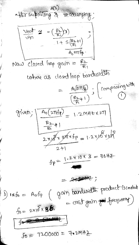
 2.103 An inverting amplifier with nominal gain of-50 VIV employs an op amp having a dc gain of 10 and a unity-gain frequency of 10 Hz. What is the 3-dB frequency fd of the closed-loop amplifier? What is its gain at 0.1 fsd andat 10fsdB?
4. A non-inverting amplifier shown below is to be constructed with a uA741C Op. Amp. It...
 4. A non-inverting amplifier shown below is to be constructed with a uA741C Op. Amp. It is to have a gain of 1001 with R1=100 ohms. Assume the GBP (non- inverting) = 100 kHz (a) Specify value of the resistor R2. (b) Sketch the Bode plot for this amplifier using specific numerical values and indicate the cut-off frequency. R R1 B Op-amp + +o VO TH
4. A non-inverting amplifier shown below is to be constructed with a uA 741C Op. Amp....
 4. A non-inverting amplifier shown below is to be constructed with a uA 741C Op. Amp. It is to have a gain of 1001 with R1=100 ohms. Assume the GBP (non- inverting) = 100 kHz (a) Specify value of the resistor R2. (b) Sketch the Bode plot for this amplifier using specific numerical values and indicate the cut-off frequency. R2 R w B Op-amp + + o V HU TH
5.8 a) Design an inverting amplifier with a gain of 4. Use an ideal op amp,...
5.8 a) Design an inverting amplifier with a gain of 4. Use an ideal op amp, a resistor in the feedback path, and 12 V power supplies. b) Using your design from part (a), determine the range of input voltages that will keep the op amp in its linear operating region. c) Suppose you wish to amplify a 2 V signal, using your design from part (a) with a variable feedback resistor. What is the largest value of feedback resistance...
Op-Amp Circuit Stability Although op-amps behave as single-pole amplifiers which are "uncondition...
 Op-Amp Circuit Stability Although op-amps behave as single-pole amplifiers which are "unconditionally stable," it's still possible to make unstable amplifiers if you don't know what you're doing. The most famous example of this is the voltage differentiator 1. Consider the following circuit: a. Find the expression for this amplifier's ideal gain Aco (s), assuming the op-amp is ideal (a(s) - o. Hint: It's just an inverting amplifier with z and z2 R (5pts) b. Suppose the gain-setting components have values...
An op-amp is to be selected for an inverting amplifier to be used at dc and...
 An op-amp is to be selected for an inverting amplifier to be
used at dc and very low frequencies. A closed-loop nominal gain 0f
-100 is desired. Specifications indicate the minimum value of dc
open-loop gain cannot exceed 0.1dB. Assume in the design of problem
with the following additional specifications given:
dc output due to input offset voltage
100mV
dc output due to input offset voltage
5mV
Determine the maximum value of input offset voltage allowed for
the op-amp. If...
An op-amp is to be selected for an inverting amplifier to be
used at dc and very low frequencies. A closed-loop nominal gain 0f
-100 is desired. Specifications indicate the minimum value of dc
open-loop gain cannot exceed 0.1dB. Assume in the design of problem
with the following additional specifications given:
dc output due to input offset voltage
100mV
dc output due to input offset voltage
5mV
Determine the maximum value of input offset voltage allowed for
the op-amp. If...
You have an otherwise ideal op-amp with an open-loop gain of 20. Design an inverting amplifier...
You have an otherwise ideal op-amp with an open-loop gain of 20. Design an inverting amplifier with this single op-amp so that it has a DC gain of -5 ±0.1. Also, please explain how this design works in words.
 4. A sinusoidal signal was used as the input to the inverting amplifier below. The op amp is ideal except for its open-loop gain. It has an open loop de gain (Ao) of 100dB and a unity-gain bandwidth (f) of 100 MHz. a) Find the transfer function, H(o), including the non-ideal open loop gain, A. b) Find the 3-dB frequency for the op amp, and sketch the |Al vs. frequency graph. Label the open loop de gain, 3-dB frequency, and...
 2. Consider this non-inverting op-amp amplifier This non-inverting amplifier circuit uses an operational amplifier as a building block. Do around. The op-amp's gain is a "little a"), but the overall amplifier's gain is A Cbig A. Derive the value of the output voltage, ve, as a function of the input voltage not confuse the non-inverting amplifier with the operational amplifier that it is built a. and the op-amp's gain a. What is the overall amplifier's gain Avo/v? (20pts) b. We...
 2.103 An inverting amplifier with nominal gain of-50 VIV employs an op amp having a dc gain of 10 and a unity-gain frequency of 10 Hz. What is the 3-dB frequency fd of the closed-loop amplifier? What is its gain at 0.1 fsd andat 10fsdB?
 4. A non-inverting amplifier shown below is to be constructed with a uA741C Op. Amp. It is to have a gain of 1001 with R1=100 ohms. Assume the GBP (non- inverting) = 100 kHz (a) Specify value of the resistor R2. (b) Sketch the Bode plot for this amplifier using specific numerical values and indicate the cut-off frequency. R R1 B Op-amp + +o VO TH
 4. A non-inverting amplifier shown below is to be constructed with a uA 741C Op. Amp. It is to have a gain of 1001 with R1=100 ohms. Assume the GBP (non- inverting) = 100 kHz (a) Specify value of the resistor R2. (b) Sketch the Bode plot for this amplifier using specific numerical values and indicate the cut-off frequency. R2 R w B Op-amp + + o V HU TH
 4. A non-inverting amplifier shown below is to be constructed with a uA 741C Op. Amp. It is to have a gain of 1001 with R1=100 ohms. Assume the GBP (non- inverting) = 100 kHz (a) Specify value of the resistor R2. (b) Sketch the Bode plot for this amplifier using specific numerical values and indicate the cut-off frequency. R2 R w B Op-amp + + o V HU TH
 Op-Amp Circuit Stability Although op-amps behave as single-pole amplifiers which are "unconditionally stable," it's still possible to make unstable amplifiers if you don't know what you're doing. The most famous example of this is the voltage differentiator 1. Consider the following circuit: a. Find the expression for this amplifier's ideal gain Aco (s), assuming the op-amp is ideal (a(s) - o. Hint: It's just an inverting amplifier with z and z2 R (5pts) b. Suppose the gain-setting components have values...
 An op-amp is to be selected for an inverting amplifier to be
used at dc and very low frequencies. A closed-loop nominal gain 0f
-100 is desired. Specifications indicate the minimum value of dc
open-loop gain cannot exceed 0.1dB. Assume in the design of problem
with the following additional specifications given:
dc output due to input offset voltage
100mV
dc output due to input offset voltage
5mV
Determine the maximum value of input offset voltage allowed for
the op-amp. If...
An op-amp is to be selected for an inverting amplifier to be
used at dc and very low frequencies. A closed-loop nominal gain 0f
-100 is desired. Specifications indicate the minimum value of dc
open-loop gain cannot exceed 0.1dB. Assume in the design of problem
with the following additional specifications given:
dc output due to input offset voltage
100mV
dc output due to input offset voltage
5mV
Determine the maximum value of input offset voltage allowed for
the op-amp. If...
Most questions answered within 3 hours.
-
While rotating the tires on your car you notice a rock [mass =
0.1 Kg] stuck...
asked 31 minutes ago -
Using MARS simulator, write MIPS programs according to
the following scenarios: Receive a positive integer number...
asked 2 hours ago -
An object in front of a concave mirror has a real image that is
11.5 cm...
asked 2 hours ago -
Consider the reaction, C3 H8 + O2 --> CO2 + H2O. How many
moles of O2...
asked 4 hours ago -
You and your opponent both roll a fair die. If you both roll the
same number,...
asked 4 hours ago -
In a study of the accuracy of fast food drive-through orders,
Restaurant A had 257 accurate...
asked 4 hours ago -
Identify and describe in detail the four categories of
institutions that could be included in a...
asked 4 hours ago -
In python
class Customer:
def __init__(self, customer_id, last_name, first_name, phone_number, address):
self._customer_id = int(customer_id)
self._last_name =...
asked 4 hours ago -
What is an example of a limitation in implementing a new
ERP system and how it...
asked 4 hours ago -
In a section of 9.7cm of an artery with a radius of 2.6mm there
is a...
asked 4 hours ago -
the two carboxylic acid groups of aspartic acid have different
acidities with pKa values of 2.1...
asked 4 hours ago -
Would CuCO3 aqueous salt combined with calcium chloride
form a solid precipitate? If so, what would...
asked 4 hours ago