
Homework Answers

Add Answer to:
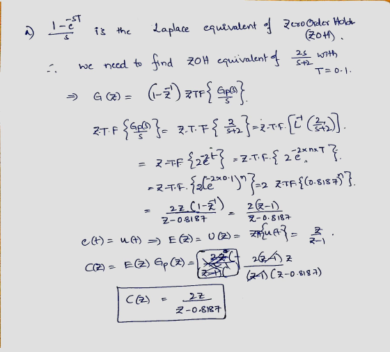
1. Given the following discrete-time open loop system: BOE (91-6" 6,0) = 2.0, TSS+2_ e(t) =...
The open loop transfer function of a discrete-time system is given by k (z+0.9) G (2)...
 The open loop transfer function of a discrete-time system is given by k (z+0.9) G (2) = (z-1)(z-0.7) i) Draw the root locus for the system for variations in the value of K ii) Determine the marginal value of K for stability.
Please only solve part C Assume the following state space representation of a discrete-time servomotor system. (As a review for the Final Exam, you might check this state space representation with th...
 Please only solve part C
Assume the following state space representation of a discrete-time servomotor system. (As a review for the Final Exam, you might check this state space representation with the difference equation in Problem 1 on Homework 2. This parenthetical comment is not a required part for Homework 8.) 2. 0.048371 u(n) 1.9048x(n) lo.04679 [1,0]x(n) y(n) Compute the open-loop eigenvalues of the system. That is, find the eigenvalues of Ф. Check controllability of the system. Or, answer the...
Please only solve part C
Assume the following state space representation of a discrete-time servomotor system. (As a review for the Final Exam, you might check this state space representation with the difference equation in Problem 1 on Homework 2. This parenthetical comment is not a required part for Homework 8.) 2. 0.048371 u(n) 1.9048x(n) lo.04679 [1,0]x(n) y(n) Compute the open-loop eigenvalues of the system. That is, find the eigenvalues of Ф. Check controllability of the system. Or, answer the...
1- Let's consider an LTI system with an impulse response of where Wo a) Find H(s) and the associa...
 1- Let's consider an LTI system with an impulse response of where Wo a) Find H(s) and the associated H(ja) b) For the cases of μ:0.2, 0.5, 1.0, and 2.0 sketch frequency spectra c) What type of filter can this system represent? d) How does the spectrum HI(jw) change as μ increases? Explain? 2- Consider the following waveform f(t) which is a one cycle of a sinusoid for 0 t π in seconds while zero elsewhere (Aperiodic Signal) fit) 10...
1. Consider the circuit shown below. Cl e, (0) c, e。(t) Find the transfer function below using t...
 Please help with this dynamics circuit
analysis.
Please show work and explain.
Thank you!!
1. Consider the circuit shown below. Cl e, (0) c, e。(t) Find the transfer function below using time-domain and impedance methods. (a) Determine the differential equation for the relationship between eo(1) and e(1) (b) Find the transfer function E, (s)/E,(s) and determine the system time constant in terms of the circuit element values C, C, and R 17 2 (c) Find the transfer function E, (s)/E,...
Please help with this dynamics circuit
analysis.
Please show work and explain.
Thank you!!
1. Consider the circuit shown below. Cl e, (0) c, e。(t) Find the transfer function below using time-domain and impedance methods. (a) Determine the differential equation for the relationship between eo(1) and e(1) (b) Find the transfer function E, (s)/E,(s) and determine the system time constant in terms of the circuit element values C, C, and R 17 2 (c) Find the transfer function E, (s)/E,...
The state space model of an interconnected three tank water storage system is given by the following equation -3 1 o 1[hi] dt The heights of water in the tanks are, respectively, hi, h2, hz. Each tan...
 The state space model of an interconnected three tank water storage system is given by the following equation -3 1 o 1[hi] dt The heights of water in the tanks are, respectively, hi, h2, hz. Each tank has an independent input flow; the volume flow rates of input water into the three tanks are, respectively, qii,qi2, Oi3. Each tank also has a water discharge outlet and the volume flow rates of water coming out of the tanks are, respectively, qo1,...
The state space model of an interconnected three tank water storage system is given by the following equation: -3 1 0 1rh dt os lo 0 3] 10 1-3 The heights of water in the tanks are, respectively,...
 The state space model of an interconnected three tank water storage system is given by the following equation: -3 1 0 1rh dt os lo 0 3] 10 1-3 The heights of water in the tanks are, respectively, h,h2,h3. Each tank has an independent input flow; the volume flow rates of input water into the three tanks are, respectively, qǐ1,W2,4a. Each tank also has a water discharge outlet and the volume flow rates of water coming out of the tanks...
(a) Determine the Fourier transform of x(t) 26(t-1)-6(t-3) (b) Compute the convolution sum of the following signals, (6%) [696] (c) The Fourier transform of a continuous-time signal a(t) is given bel...
 (a) Determine the Fourier transform of x(t) 26(t-1)-6(t-3) (b) Compute the convolution sum of the following signals, (6%) [696] (c) The Fourier transform of a continuous-time signal a(t) is given below. Determine the [696] total energy of (t) 4 sin w (d) Determine the DC value and the average power of the following periodic signal. (6%) 0.5 0.5 (e) Determine the Nyquist rate for the following signal. (6%) x(t) = [1-0.78 cos(50nt + π/4)]2. (f) Sketch the frequency spectrum of...
Problem 2 Wis) R(s) U(s) Gol (s) D a (s) E(s) H(s) Given a system as in the diagram above, use MATLAB to solve the problems: Assume we want the closed-loop system rise time to be t, 0.18 sec S + Z H(...
 Problem 2 Wis) R(s) U(s) Gol (s) D a (s) E(s) H(s) Given a system as in the diagram above, use MATLAB to solve the problems: Assume we want the closed-loop system rise time to be t, 0.18 sec S + Z H(s) 1 Gpl)s(s+)et s(s 1) s + p a) Assume W(s)-0. Draw the root locus of the system assuming compensator consists only of the adjustable gain parameter K, i.e. Dct (s) Determine the approximate range of values of...
winkngs spring i(t) v(t) st VEE Figure 1: (a)Solenoid with retu spring. (b) Equivalent lumped electrical cireuit (...
 winkngs spring i(t) v(t) st VEE Figure 1: (a)Solenoid with retu spring. (b) Equivalent lumped electrical cireuit (e) Equivalent mechanical diagram Figure 1(a) illustrates a solenoid with a return spring The voltage e(t) across the winding, causes a current it) to flow through the winding. which in turn generates a magnetic field The magnetic field induces a force f(t) on the plunger mass, . The magnitude of this force is related to the current in the windings via the solenoid's...
solve quastion 3,4 and 5 B. Tasks and Guide 1. System description and Mathematical modeling The...
 solve quastion 3,4 and 5
B. Tasks and Guide 1. System description and Mathematical modeling The antenna positioning system is shown in Fig. 1. In this problem we consider the yaw angle control system, where 0(t) is the yaw angle. Suppose that the gain of the power amplifier is 5 , and that the gear ratio and the angle sensor (the shaft encoder and the data hold) are such that (t)= 0.40(t) where the units of v,(t) are volts and...
solve quastion 3,4 and 5
B. Tasks and Guide 1. System description and Mathematical modeling The antenna positioning system is shown in Fig. 1. In this problem we consider the yaw angle control system, where 0(t) is the yaw angle. Suppose that the gain of the power amplifier is 5 , and that the gear ratio and the angle sensor (the shaft encoder and the data hold) are such that (t)= 0.40(t) where the units of v,(t) are volts and...
 The open loop transfer function of a discrete-time system is given by k (z+0.9) G (2) = (z-1)(z-0.7) i) Draw the root locus for the system for variations in the value of K ii) Determine the marginal value of K for stability.
 Please only solve part C
Assume the following state space representation of a discrete-time servomotor system. (As a review for the Final Exam, you might check this state space representation with the difference equation in Problem 1 on Homework 2. This parenthetical comment is not a required part for Homework 8.) 2. 0.048371 u(n) 1.9048x(n) lo.04679 [1,0]x(n) y(n) Compute the open-loop eigenvalues of the system. That is, find the eigenvalues of Ф. Check controllability of the system. Or, answer the...
Please only solve part C
Assume the following state space representation of a discrete-time servomotor system. (As a review for the Final Exam, you might check this state space representation with the difference equation in Problem 1 on Homework 2. This parenthetical comment is not a required part for Homework 8.) 2. 0.048371 u(n) 1.9048x(n) lo.04679 [1,0]x(n) y(n) Compute the open-loop eigenvalues of the system. That is, find the eigenvalues of Ф. Check controllability of the system. Or, answer the...
 1- Let's consider an LTI system with an impulse response of where Wo a) Find H(s) and the associated H(ja) b) For the cases of μ:0.2, 0.5, 1.0, and 2.0 sketch frequency spectra c) What type of filter can this system represent? d) How does the spectrum HI(jw) change as μ increases? Explain? 2- Consider the following waveform f(t) which is a one cycle of a sinusoid for 0 t π in seconds while zero elsewhere (Aperiodic Signal) fit) 10...
 Please help with this dynamics circuit
analysis.
Please show work and explain.
Thank you!!
1. Consider the circuit shown below. Cl e, (0) c, e。(t) Find the transfer function below using time-domain and impedance methods. (a) Determine the differential equation for the relationship between eo(1) and e(1) (b) Find the transfer function E, (s)/E,(s) and determine the system time constant in terms of the circuit element values C, C, and R 17 2 (c) Find the transfer function E, (s)/E,...
Please help with this dynamics circuit
analysis.
Please show work and explain.
Thank you!!
1. Consider the circuit shown below. Cl e, (0) c, e。(t) Find the transfer function below using time-domain and impedance methods. (a) Determine the differential equation for the relationship between eo(1) and e(1) (b) Find the transfer function E, (s)/E,(s) and determine the system time constant in terms of the circuit element values C, C, and R 17 2 (c) Find the transfer function E, (s)/E,...
 The state space model of an interconnected three tank water storage system is given by the following equation -3 1 o 1[hi] dt The heights of water in the tanks are, respectively, hi, h2, hz. Each tank has an independent input flow; the volume flow rates of input water into the three tanks are, respectively, qii,qi2, Oi3. Each tank also has a water discharge outlet and the volume flow rates of water coming out of the tanks are, respectively, qo1,...
 The state space model of an interconnected three tank water storage system is given by the following equation: -3 1 0 1rh dt os lo 0 3] 10 1-3 The heights of water in the tanks are, respectively, h,h2,h3. Each tank has an independent input flow; the volume flow rates of input water into the three tanks are, respectively, qǐ1,W2,4a. Each tank also has a water discharge outlet and the volume flow rates of water coming out of the tanks...
 (a) Determine the Fourier transform of x(t) 26(t-1)-6(t-3) (b) Compute the convolution sum of the following signals, (6%) [696] (c) The Fourier transform of a continuous-time signal a(t) is given below. Determine the [696] total energy of (t) 4 sin w (d) Determine the DC value and the average power of the following periodic signal. (6%) 0.5 0.5 (e) Determine the Nyquist rate for the following signal. (6%) x(t) = [1-0.78 cos(50nt + π/4)]2. (f) Sketch the frequency spectrum of...
 Problem 2 Wis) R(s) U(s) Gol (s) D a (s) E(s) H(s) Given a system as in the diagram above, use MATLAB to solve the problems: Assume we want the closed-loop system rise time to be t, 0.18 sec S + Z H(s) 1 Gpl)s(s+)et s(s 1) s + p a) Assume W(s)-0. Draw the root locus of the system assuming compensator consists only of the adjustable gain parameter K, i.e. Dct (s) Determine the approximate range of values of...
 winkngs spring i(t) v(t) st VEE Figure 1: (a)Solenoid with retu spring. (b) Equivalent lumped electrical cireuit (e) Equivalent mechanical diagram Figure 1(a) illustrates a solenoid with a return spring The voltage e(t) across the winding, causes a current it) to flow through the winding. which in turn generates a magnetic field The magnetic field induces a force f(t) on the plunger mass, . The magnitude of this force is related to the current in the windings via the solenoid's...
 solve quastion 3,4 and 5
B. Tasks and Guide 1. System description and Mathematical modeling The antenna positioning system is shown in Fig. 1. In this problem we consider the yaw angle control system, where 0(t) is the yaw angle. Suppose that the gain of the power amplifier is 5 , and that the gear ratio and the angle sensor (the shaft encoder and the data hold) are such that (t)= 0.40(t) where the units of v,(t) are volts and...
solve quastion 3,4 and 5
B. Tasks and Guide 1. System description and Mathematical modeling The antenna positioning system is shown in Fig. 1. In this problem we consider the yaw angle control system, where 0(t) is the yaw angle. Suppose that the gain of the power amplifier is 5 , and that the gear ratio and the angle sensor (the shaft encoder and the data hold) are such that (t)= 0.40(t) where the units of v,(t) are volts and...
Most questions answered within 3 hours.
-
Create a balanced compensation plan that you feel would
encourage a restaurant manager to be more...
asked 1 second ago -
Re: Human Physiology
Comment on the differences between representing V02 max as an
absolute number and...
asked 2 minutes ago -
A firm with a WACC of 10% is considering the following mutually
exclusive projects:
0
1...
asked 7 minutes ago -
. A 100.0 mL sample of 0.18 M HClO4 is titrated with 0.27 M
LiOH. Determine...
asked 30 minutes ago -
A regression equation that describes the relationship between
the amount of the bill ($) at a...
asked 1 hour ago -
exercise on VSEPR and molecular structrue.
octahedral
SeCl62-
TeCl62-
ClF62-
distorted
SeF62–
IF6–
asked 1 hour ago -
284 mL of a 0.52 M potassium hydroxide solution is added to 467
mL of a...
asked 1 hour ago -
Little’s Law: Val d’Costa is a world famous ski village in the
French Alps. Because of...
asked 2 hours ago -
Find the absolute error D for the calculation if A + B/C=D A=
9.4 +/- 0.4...
asked 3 hours ago -
New Air Heating and Cooling, manufactures furnaces and central
air units. The company pride itself on...
asked 3 hours ago -
A coach uses a new technique to train gymnasts. Seven
gymnasts were randomly selected and their...
asked 5 hours ago -
While rotating the tires on your car you notice a rock [mass =
0.1 Kg] stuck...
asked 7 hours ago