
Homework Answers


1)matlab code and result
clear;clc;
%% part (a)
Gpl=tf([1],[1 1 0]);
Ls1=Gpl*1;
figure(1);
rlocus(Ls1);
title('Rootlocus plot for proportional controller');
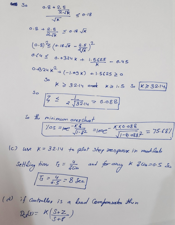
%% part (c)
k1=32.14;
M1=feedback(k1*Ls1,1);
figure(2);
step(M1);
title('step response for proportional controller at required
tr');
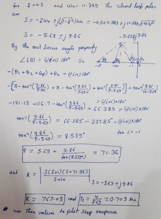
%% part (d)
Dcl=tf([1 10],[1 71.36]);
Ls2=Gpl*Dcl;
figure(3);
rlocus(Ls2);
title('Rootlocus plot for lead compensator');
k2=767.05;
M2=feedback(k2*Ls2,1);
figure(4);
step(M2);
title('step response for lead compensator at required tr');


if you compare both step response the lead compensated response have small rise time and small overshoot
Add Answer to:
Problem 2 Wis) R(s) U(s) Gol (s) D a (s) E(s) H(s) Given a system as in the diagram above, use MATLAB to solve the problems: Assume we want the closed-loop system rise time to be t, 0.18 sec S + Z H(...
Please solve part b and c and d !! Consider the closed loop system shown in...
 Please solve part b and c and d !!
Consider the closed loop system shown in Figure 4. The root locus of that system is shown in Figure 5 (s+40s+8) R(s) Y(s) Figure 4 System block diagram of Problem 4 a) On the root locus plot, sketch the region of possible roots of the dominant closed-loop poles such that the system response to a unit step has the following time domain specifications. [5] i. Damping ratio, 20.76 ii. Natural frequency,....
Please solve part b and c and d !!
Consider the closed loop system shown in Figure 4. The root locus of that system is shown in Figure 5 (s+40s+8) R(s) Y(s) Figure 4 System block diagram of Problem 4 a) On the root locus plot, sketch the region of possible roots of the dominant closed-loop poles such that the system response to a unit step has the following time domain specifications. [5] i. Damping ratio, 20.76 ii. Natural frequency,....
Wis) R(s u(s) 14 Gl(s) H(s) Given a system as in the diagram above, where K is an adjustable pa...
 Wis) R(s u(s) 14 Gl(s) H(s) Given a system as in the diagram above, where K is an adjustable parameter pl(s) Dal(sKp+ g) Assuming W-0, find the transfer function Y(s)/R(s) h) Assuming R-0, find the transfer function Y(s)/W(s) i) What is the type of the system (with respect to steady-state error)? j) What is the steady-state error when rt)u(t) (unit-step) and w(t)-0 k) What is the s.s. error when r(t) t u(t) and w(t)-0 ) Assume r(t)-0, what is the...
only b and c please 1 Consider the system whose transfer function is given by: G(S)...
 only b and c please
1 Consider the system whose transfer function is given by: G(S) == (2s +1)(s+3) unction is given by: G(s) - (a) Use the root-locus design methodology to design a lead compensator that will provide a closed-loop damping 5 =0.4 and a natural frequency on =9 rad/sec. The general transfer function for lead compensation is given by D(5)=K (977), p>z, 2=2 (b) Use MATLAB to plot the root locus of the feed-forward transfer function, D(s)*G(s), and...
only b and c please
1 Consider the system whose transfer function is given by: G(S) == (2s +1)(s+3) unction is given by: G(s) - (a) Use the root-locus design methodology to design a lead compensator that will provide a closed-loop damping 5 =0.4 and a natural frequency on =9 rad/sec. The general transfer function for lead compensation is given by D(5)=K (977), p>z, 2=2 (b) Use MATLAB to plot the root locus of the feed-forward transfer function, D(s)*G(s), and...
A system having an open loop transfer function of G(S) = K10/(S+2)(3+1) has a root locus...
 A system having an open loop transfer function of G(S) = K10/(S+2)(3+1) has a root locus plot as shown below. The location of the roots for a system gain of K= 0.248 is show on the plot. At this location the system has a damping factor of 0.708 and a settling time of 4/1.5 = 2.67 seconds. A lead compensator is to be used to improve the transient response. (Note that nothing is plotted on the graph except for that...
Consider the automobile cruise-control system shown below: Engine ActuatorCarburetor 0.833 and load 40 3s +1 Compensator R(s)E(s) Ge(s) s +1 -t e(t) Sensor 0.03 1) Derive the closed-loop transfer fun...
 Consider the automobile cruise-control system shown below: Engine ActuatorCarburetor 0.833 and load 40 3s +1 Compensator R(s)E(s) Ge(s) s +1 -t e(t) Sensor 0.03 1) Derive the closed-loop transfer function of V(s)/R(s) when Gc(s)-1 2) Derive the closed-loop transfer function of E(s)/R(s) when Ge(s)-1 3) Plot the time history of the error e(t) of the closed-loop system when r(t) is a unit step input. 4) Plot the root-loci of the uncompensated system (when Gc(s)-1). Mark the closed-loop complex poles on...
QI: For the following closed loop system below: RCS — -*H 00 For each of the...
 QI: For the following closed loop system below: RCS — -*H 00 For each of the following open loop transfer function Ls): D) L(S) 842)(5) I L ) - +1 (5+1)(5+5)(5+) III) L(S) - 3421(+3) a) Draw the root locus and find the range of k for which the closed-loop system is stable. b) Find the value of k so that the system is marginally stable, and for that value, find the oscillation frequency of the time response. c) Find...
02: For the following closed loop system below: R(s) or L(s) = (s B's ey draw the root locus stab...
 02: For the following closed loop system below: R(s) or L(s) = (s B's ey draw the root locus stable a) and find the range ofk for which the closed loop system, s (s-B)(S-C) b) for Ls) -GrsmisrG draw the root locus and find the range of k for which the closed loop system is (s+A)(s+B)(s+C) stable. c) For (a) and (b), find.: 1 the value of K so that the system is marginally stable, and for that value, find...
1. Using the MATLAB rltool command (or rlocus and rlocfind), plot the K > 0 root...
 1. Using the MATLAB rltool command (or rlocus and rlocfind), plot the K > 0 root locus for What is the value of the largest damping ra- 2+2s+1 s(s120)7,7 -2,12). 1 + KL(s) = 0, where L(s) = tio associated with the pair of complex poles? At which value of K is it achieved? Turn in a printout of your plot showing the location of the poles on the damping ratio line that you found. 2. Suppose the unity feedback...
3. Consider the tilt control block diagram shown below R(s) DesiredG(s) 12 s(s+10)(s+70) Y(s) Til...
 3. Consider the tilt control block diagram shown below R(s) DesiredG(s) 12 s(s+10)(s+70) Y(s) Tilt tilt Design specifications require an overshoot of less than 5% and a settling time of less than 0.6 seconds. (a) Use MATLAB to sketch the root locus (rlocus command) with a proportional controller and use the root locus to determine a value for K (if any) that will satisfy the design requirements (b) Design a lead compensator Ge(s) to satisfy the design specifications. You can...
Determine: 1. The transfer function C(s)/R(s). Also find the closed-loop poles of the system. 2. The...
 Determine: 1. The transfer function C(s)/R(s). Also find the
closed-loop poles of the system. 2. The values of the undamped
natural frequency ωN and damping ratio ξ of the closed-loop poles.
3. The expressions of the rise time, the peak time, the maximum
overshoot, and the 2% settling time due to a unit-step reference
signal.
For the open-loop process with negative feedback R(S) Gp(S) C(s) H(s) 103 Go(s) = 1 , Gp(s)- s(s + 4) Determine: 1. The transfer function...
Determine: 1. The transfer function C(s)/R(s). Also find the
closed-loop poles of the system. 2. The values of the undamped
natural frequency ωN and damping ratio ξ of the closed-loop poles.
3. The expressions of the rise time, the peak time, the maximum
overshoot, and the 2% settling time due to a unit-step reference
signal.
For the open-loop process with negative feedback R(S) Gp(S) C(s) H(s) 103 Go(s) = 1 , Gp(s)- s(s + 4) Determine: 1. The transfer function...
 Please solve part b and c and d !!
Consider the closed loop system shown in Figure 4. The root locus of that system is shown in Figure 5 (s+40s+8) R(s) Y(s) Figure 4 System block diagram of Problem 4 a) On the root locus plot, sketch the region of possible roots of the dominant closed-loop poles such that the system response to a unit step has the following time domain specifications. [5] i. Damping ratio, 20.76 ii. Natural frequency,....
Please solve part b and c and d !!
Consider the closed loop system shown in Figure 4. The root locus of that system is shown in Figure 5 (s+40s+8) R(s) Y(s) Figure 4 System block diagram of Problem 4 a) On the root locus plot, sketch the region of possible roots of the dominant closed-loop poles such that the system response to a unit step has the following time domain specifications. [5] i. Damping ratio, 20.76 ii. Natural frequency,....
 Wis) R(s u(s) 14 Gl(s) H(s) Given a system as in the diagram above, where K is an adjustable parameter pl(s) Dal(sKp+ g) Assuming W-0, find the transfer function Y(s)/R(s) h) Assuming R-0, find the transfer function Y(s)/W(s) i) What is the type of the system (with respect to steady-state error)? j) What is the steady-state error when rt)u(t) (unit-step) and w(t)-0 k) What is the s.s. error when r(t) t u(t) and w(t)-0 ) Assume r(t)-0, what is the...
 only b and c please
1 Consider the system whose transfer function is given by: G(S) == (2s +1)(s+3) unction is given by: G(s) - (a) Use the root-locus design methodology to design a lead compensator that will provide a closed-loop damping 5 =0.4 and a natural frequency on =9 rad/sec. The general transfer function for lead compensation is given by D(5)=K (977), p>z, 2=2 (b) Use MATLAB to plot the root locus of the feed-forward transfer function, D(s)*G(s), and...
only b and c please
1 Consider the system whose transfer function is given by: G(S) == (2s +1)(s+3) unction is given by: G(s) - (a) Use the root-locus design methodology to design a lead compensator that will provide a closed-loop damping 5 =0.4 and a natural frequency on =9 rad/sec. The general transfer function for lead compensation is given by D(5)=K (977), p>z, 2=2 (b) Use MATLAB to plot the root locus of the feed-forward transfer function, D(s)*G(s), and...
 A system having an open loop transfer function of G(S) = K10/(S+2)(3+1) has a root locus plot as shown below. The location of the roots for a system gain of K= 0.248 is show on the plot. At this location the system has a damping factor of 0.708 and a settling time of 4/1.5 = 2.67 seconds. A lead compensator is to be used to improve the transient response. (Note that nothing is plotted on the graph except for that...
 Consider the automobile cruise-control system shown below: Engine ActuatorCarburetor 0.833 and load 40 3s +1 Compensator R(s)E(s) Ge(s) s +1 -t e(t) Sensor 0.03 1) Derive the closed-loop transfer function of V(s)/R(s) when Gc(s)-1 2) Derive the closed-loop transfer function of E(s)/R(s) when Ge(s)-1 3) Plot the time history of the error e(t) of the closed-loop system when r(t) is a unit step input. 4) Plot the root-loci of the uncompensated system (when Gc(s)-1). Mark the closed-loop complex poles on...
 QI: For the following closed loop system below: RCS — -*H 00 For each of the following open loop transfer function Ls): D) L(S) 842)(5) I L ) - +1 (5+1)(5+5)(5+) III) L(S) - 3421(+3) a) Draw the root locus and find the range of k for which the closed-loop system is stable. b) Find the value of k so that the system is marginally stable, and for that value, find the oscillation frequency of the time response. c) Find...
 02: For the following closed loop system below: R(s) or L(s) = (s B's ey draw the root locus stable a) and find the range ofk for which the closed loop system, s (s-B)(S-C) b) for Ls) -GrsmisrG draw the root locus and find the range of k for which the closed loop system is (s+A)(s+B)(s+C) stable. c) For (a) and (b), find.: 1 the value of K so that the system is marginally stable, and for that value, find...
 1. Using the MATLAB rltool command (or rlocus and rlocfind), plot the K > 0 root locus for What is the value of the largest damping ra- 2+2s+1 s(s120)7,7 -2,12). 1 + KL(s) = 0, where L(s) = tio associated with the pair of complex poles? At which value of K is it achieved? Turn in a printout of your plot showing the location of the poles on the damping ratio line that you found. 2. Suppose the unity feedback...
 3. Consider the tilt control block diagram shown below R(s) DesiredG(s) 12 s(s+10)(s+70) Y(s) Tilt tilt Design specifications require an overshoot of less than 5% and a settling time of less than 0.6 seconds. (a) Use MATLAB to sketch the root locus (rlocus command) with a proportional controller and use the root locus to determine a value for K (if any) that will satisfy the design requirements (b) Design a lead compensator Ge(s) to satisfy the design specifications. You can...
 Determine: 1. The transfer function C(s)/R(s). Also find the
closed-loop poles of the system. 2. The values of the undamped
natural frequency ωN and damping ratio ξ of the closed-loop poles.
3. The expressions of the rise time, the peak time, the maximum
overshoot, and the 2% settling time due to a unit-step reference
signal.
For the open-loop process with negative feedback R(S) Gp(S) C(s) H(s) 103 Go(s) = 1 , Gp(s)- s(s + 4) Determine: 1. The transfer function...
Determine: 1. The transfer function C(s)/R(s). Also find the
closed-loop poles of the system. 2. The values of the undamped
natural frequency ωN and damping ratio ξ of the closed-loop poles.
3. The expressions of the rise time, the peak time, the maximum
overshoot, and the 2% settling time due to a unit-step reference
signal.
For the open-loop process with negative feedback R(S) Gp(S) C(s) H(s) 103 Go(s) = 1 , Gp(s)- s(s + 4) Determine: 1. The transfer function...
Most questions answered within 3 hours.
-
Write a program to solve the Josephus problem, with the following
modification:
Sample Input:
./a.out n...
asked 29 minutes ago -
At the start of a CD it is spinning at a rate of 525 rpm
(revolutions...
asked 1 hour ago -
4. Without doing any calculations, predict whether the observed
∆T would increase, decrease or remain the...
asked 2 hours ago -
Based on the range, which of the following sets of scores has
the greatest variability? 3,...
asked 3 hours ago -
Ripples in a pond travel at a velocity of 3 m/s with one peak
passing a...
asked 3 hours ago -
A man stands on the roof of a building of height 13.0 mm and
throws a...
asked 3 hours ago -
The extent to which assets are financed by borrowed funds and
other liabilities is indicated by:...
asked 4 hours ago -
Explain in detail
Germany is the fifth largest economy
explain what goods and services Germany specializes...
asked 4 hours ago -
The density of platinum is 21.45 g/mL. If a cube of platinum
with a mass of...
asked 4 hours ago -
Accounts Receivable
Sales
A/R Posting
Extended Sales Invoice
Packing Slip
Compare invoice to packing slip 2...
asked 4 hours ago -
Michaella, age 23, is a full-time law student and is claimed by
her parents as a...
asked 4 hours ago -
Why are polymers not typically casted into products?
asked 5 hours ago