
Homework Answers


Add Answer to:
1. Response of the RL circuit - After having been in position 1 for a long...
3. UMF 5.33 5.33 After having been in position 1 for a long time, the switch...
 3. UMF 5.33 5.33 After having been in position 1 for a long time, the switch in the circuit of Fig. P5.33 was moved to position 2 at t = 0. Given that Vo = 12 V, Ri = 30 k2, R2 = 120 KS2. R3 = 60 k-2, and C = 100 F, determine: (a) ic(0) and uc(0) (b) ic(O) and vc(0) (c) cic() and uc(0) (d) vci) for 10 (e) ic(t) for 1 > 0 i o e...
Problem 1 (10 points): The switch in the circuit of Fig. 1 has been in position...
 Problem 1 (10 points): The switch in the circuit of Fig. 1 has been in position a for a long time. Att 0, the switch moves to position b 1. (4 points) Construct an s-domain circuit for t> 0 2. (4 points) Find Vo(s) and vo(t) for t> 0 3. (2 points) Find IL(s) and iL () fort > 0. t-0 Ri R2 R1 = 400 ohms, R2 = 1000 ohms, C = 6.25 nF L 16 mH, and vg-360...
Please do parts A-E Course Contents , Hw6 RL Circuit Timer □Notes Evaluate Feedbo After having...
 Please do parts A-E
Course Contents , Hw6 RL Circuit Timer □Notes Evaluate Feedbo After having been in position 1 for a long time, the switch in the circuit as shown below was moved to position 2 at t-0s, were v-15v,R,-50R2- Ri l it 0 DL, R2 (a) Determine (O') and Vi(O'") (A): VL(O") 〔V) Submit Answer Tries 0/3 (b) Determine i(0) and V(O) (A): VIL(O) Submit Answer Tries oy3 (c) Determine I(0) and vu(o) Submit Answe Tries oy3 (d)...
Please do parts A-E
Course Contents , Hw6 RL Circuit Timer □Notes Evaluate Feedbo After having been in position 1 for a long time, the switch in the circuit as shown below was moved to position 2 at t-0s, were v-15v,R,-50R2- Ri l it 0 DL, R2 (a) Determine (O') and Vi(O'") (A): VL(O") 〔V) Submit Answer Tries 0/3 (b) Determine i(0) and V(O) (A): VIL(O) Submit Answer Tries oy3 (c) Determine I(0) and vu(o) Submit Answe Tries oy3 (d)...
Given a RL circuit as in Figure Q2 (a) with input for the circuit is vi(t)...
 Given a RL circuit as in Figure Q2 (a) with input for the circuit is vi(t) and output is vo(t). L1 il(t) R1 il(t) + + vi(t) L2 R2 v.(t) Figure Q2 (a) Show that the RL circuit in Figure Q2 (a) can be represented by the following state-space representation: di,, (t) -(R+R) L dt di,, (t) dt R₂ R L, 1.t -R, L. (1) L2 8-6 L, V. (t) L v.(t)=[R, R)
The Natural Response of an RL Circuit In summary, to find the time constant of an...
 The Natural Response of an RL Circuit In summary, to find the time constant of an RL circuit, find the Thevenin equivalent resistance se Learning Goal: To analyze an RL circuit to determine the initial current through an inductor, the time constant, and the expression for the natural response of the inductor current, and to use the expression for the inductor current to find other circuit quantities, such as current, voltage, power, or energy. The natural response of an RL...
1. Forced Response Response of RC circuit The component values for the circuit shown below are...
 1. Forced Response Response of RC circuit The component values for the circuit shown below are v' = 16 V. RI= R2 3 kQ. R3= 8 kQ. and C-25/1 F. Assume that the switch had been open for a long time prior to t-0 i is the current passing through R. v is the voltage across the capacitor. Determine (a) (or and v(or) i0and v 0 b) (o)and v(or) (c) i[oo) and v(oo (d) i(t) for t20 (e) v(t) for...
1. The switch in below circuit has been in position 1 for a long time and...
 1. The switch in below circuit has been in position 1 for a long time and the circuit is steady. At t-0, the switch moves to position 2. Find Vo(t) and (c) fort > 0. R1 1 W- § R2104 VaR2 60v S125K
Please show all work and explain steps So that I can see where I am going...
 Please show all work and explain steps So that I can see where I
am going wrong.
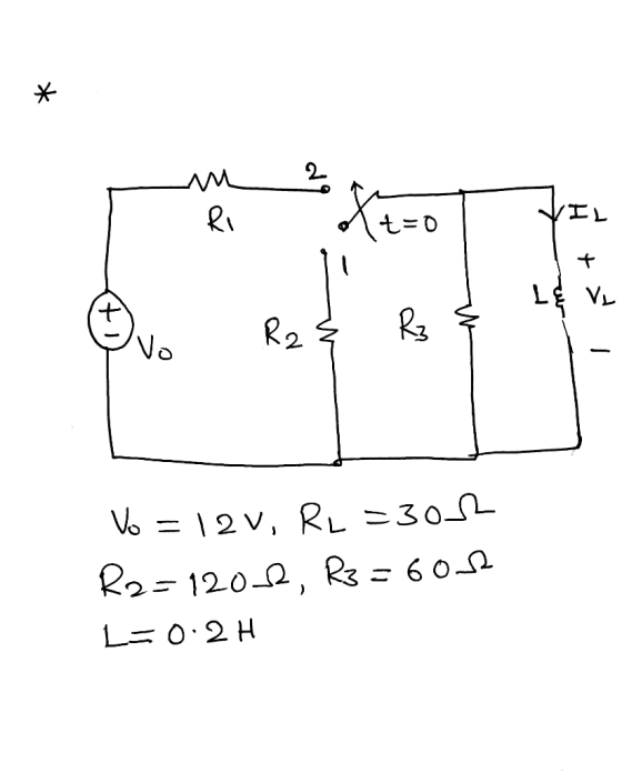
After having been in position 1 for a long time, the switch in the circuit as shown below was moved to position 2 at t-os, were Vo-14 V, R1-2 Ω, R2 = 148 Ω, R3-40 Ω, and L-1 H OL (a) Determine () and VL(O) iL(:0.000 (A); VL(o):0.000 (V) You are correct ies ur receipt no. is 146-1674 (b) Determine iL(O) and Vi(O):...
Please show all work and explain steps So that I can see where I
am going wrong.
After having been in position 1 for a long time, the switch in the circuit as shown below was moved to position 2 at t-os, were Vo-14 V, R1-2 Ω, R2 = 148 Ω, R3-40 Ω, and L-1 H OL (a) Determine () and VL(O) iL(:0.000 (A); VL(o):0.000 (V) You are correct ies ur receipt no. is 146-1674 (b) Determine iL(O) and Vi(O):...
In the circuit shown in Figure-2, the switch was in position-a for a long time. At...
 In the circuit shown in Figure-2, the switch was in position-a for a long time. At time t-0, the switch is moved to position-b. ) Att-0, calculate Vc(+). Q2: 151 1101 Solve Ve () at t20 Find Vc at t 2 sec. switch 25 Figure-2
2 First-Order RC Circuit: Natural Response The switch in the circuit in Figure 2 has been...
 2 First-Order RC Circuit: Natural Response The switch in the circuit in Figure 2 has been in position for a long time. At t = 0, the switch moves to position (the switch opens) and stays there. Assuming that V. > O for the constant voltage source, (a) find vc(0-), vc(0+), ic(0-), and ic(0+); (b) find vc(t) when t 20 (if you want, you can write vo(t) by circuit inspection; you don't need to show the differential equation); and (c)...
 3. UMF 5.33 5.33 After having been in position 1 for a long time, the switch in the circuit of Fig. P5.33 was moved to position 2 at t = 0. Given that Vo = 12 V, Ri = 30 k2, R2 = 120 KS2. R3 = 60 k-2, and C = 100 F, determine: (a) ic(0) and uc(0) (b) ic(O) and vc(0) (c) cic() and uc(0) (d) vci) for 10 (e) ic(t) for 1 > 0 i o e...
 Problem 1 (10 points): The switch in the circuit of Fig. 1 has been in position a for a long time. Att 0, the switch moves to position b 1. (4 points) Construct an s-domain circuit for t> 0 2. (4 points) Find Vo(s) and vo(t) for t> 0 3. (2 points) Find IL(s) and iL () fort > 0. t-0 Ri R2 R1 = 400 ohms, R2 = 1000 ohms, C = 6.25 nF L 16 mH, and vg-360...
 Please do parts A-E
Course Contents , Hw6 RL Circuit Timer □Notes Evaluate Feedbo After having been in position 1 for a long time, the switch in the circuit as shown below was moved to position 2 at t-0s, were v-15v,R,-50R2- Ri l it 0 DL, R2 (a) Determine (O') and Vi(O'") (A): VL(O") 〔V) Submit Answer Tries 0/3 (b) Determine i(0) and V(O) (A): VIL(O) Submit Answer Tries oy3 (c) Determine I(0) and vu(o) Submit Answe Tries oy3 (d)...
Please do parts A-E
Course Contents , Hw6 RL Circuit Timer □Notes Evaluate Feedbo After having been in position 1 for a long time, the switch in the circuit as shown below was moved to position 2 at t-0s, were v-15v,R,-50R2- Ri l it 0 DL, R2 (a) Determine (O') and Vi(O'") (A): VL(O") 〔V) Submit Answer Tries 0/3 (b) Determine i(0) and V(O) (A): VIL(O) Submit Answer Tries oy3 (c) Determine I(0) and vu(o) Submit Answe Tries oy3 (d)...
 Given a RL circuit as in Figure Q2 (a) with input for the circuit is vi(t) and output is vo(t). L1 il(t) R1 il(t) + + vi(t) L2 R2 v.(t) Figure Q2 (a) Show that the RL circuit in Figure Q2 (a) can be represented by the following state-space representation: di,, (t) -(R+R) L dt di,, (t) dt R₂ R L, 1.t -R, L. (1) L2 8-6 L, V. (t) L v.(t)=[R, R)
 The Natural Response of an RL Circuit In summary, to find the time constant of an RL circuit, find the Thevenin equivalent resistance se Learning Goal: To analyze an RL circuit to determine the initial current through an inductor, the time constant, and the expression for the natural response of the inductor current, and to use the expression for the inductor current to find other circuit quantities, such as current, voltage, power, or energy. The natural response of an RL...
 1. Forced Response Response of RC circuit The component values for the circuit shown below are v' = 16 V. RI= R2 3 kQ. R3= 8 kQ. and C-25/1 F. Assume that the switch had been open for a long time prior to t-0 i is the current passing through R. v is the voltage across the capacitor. Determine (a) (or and v(or) i0and v 0 b) (o)and v(or) (c) i[oo) and v(oo (d) i(t) for t20 (e) v(t) for...
 1. The switch in below circuit has been in position 1 for a long time and the circuit is steady. At t-0, the switch moves to position 2. Find Vo(t) and (c) fort > 0. R1 1 W- § R2104 VaR2 60v S125K
 Please show all work and explain steps So that I can see where I
am going wrong.
After having been in position 1 for a long time, the switch in the circuit as shown below was moved to position 2 at t-os, were Vo-14 V, R1-2 Ω, R2 = 148 Ω, R3-40 Ω, and L-1 H OL (a) Determine () and VL(O) iL(:0.000 (A); VL(o):0.000 (V) You are correct ies ur receipt no. is 146-1674 (b) Determine iL(O) and Vi(O):...
Please show all work and explain steps So that I can see where I
am going wrong.
After having been in position 1 for a long time, the switch in the circuit as shown below was moved to position 2 at t-os, were Vo-14 V, R1-2 Ω, R2 = 148 Ω, R3-40 Ω, and L-1 H OL (a) Determine () and VL(O) iL(:0.000 (A); VL(o):0.000 (V) You are correct ies ur receipt no. is 146-1674 (b) Determine iL(O) and Vi(O):...
 In the circuit shown in Figure-2, the switch was in position-a for a long time. At time t-0, the switch is moved to position-b. ) Att-0, calculate Vc(+). Q2: 151 1101 Solve Ve () at t20 Find Vc at t 2 sec. switch 25 Figure-2
 2 First-Order RC Circuit: Natural Response The switch in the circuit in Figure 2 has been in position for a long time. At t = 0, the switch moves to position (the switch opens) and stays there. Assuming that V. > O for the constant voltage source, (a) find vc(0-), vc(0+), ic(0-), and ic(0+); (b) find vc(t) when t 20 (if you want, you can write vo(t) by circuit inspection; you don't need to show the differential equation); and (c)...
Most questions answered within 3 hours.
-
write a java program that does the following
Part one
Use a For loop to compute...
asked 2 minutes ago -
please simplify how vapor pressure lowering is related to a
rise in the boiling point solution
asked 5 minutes ago -
"A student in another class made a claim that many people are
now talking about outlawing...
asked 4 minutes ago -
Test the hypothesis using P-value approach. Be sure to verify
the requirements of the test.
H0:...
asked 46 minutes ago -
For a voltaic cell based on the reaction below, which statement
is correct?
Zn(s)+2H+(aq)→Zn2+(aq)+H2(g)
Zn2+(aq) is...
asked 31 minutes ago -
If 20 g of Na2SO4 is reacted with 20 g of
Al(NO3)3 according to the following...
asked 22 minutes ago -
One difference between periodic and perpetual inventory systems
is:
Multiple Choice Cost of goods sold is...
asked 28 minutes ago -
Using the OSHA web site find the OSHA regulation for personal eye
protection. Write a summary...
asked 26 minutes ago -
In 600 words, answer the following
1) Why has the transfer of defense technologies to domestic...
asked 26 minutes ago -
Balance the following oxidation-reduction equations using redox
methods:
Cu + H+ --------> Cu+ +
H2
asked 47 minutes ago -
For the balanced reaction: CaCl2 (aq) + Na2CO3 (aq) -> CaCO3
(s) + 2 NaCl (aq),...
asked 41 minutes ago -
1. If ln(x)=ln(x)= -0.2 , what does xx equal? Round
your answer to three significant figures. The...
asked 38 minutes ago