
Homework Answers

Add Answer to:
Given a RL circuit as in Figure Q2 (a) with input for the circuit is vi(t)...
1. Response of the RL circuit - After having been in position 1 for a long...
 1. Response of the RL circuit - After having been in position 1 for a long time, the switch in the circuit below is moved to position 2 at the time t = 0. Given that Vo = 12 V, R1 = 3092, R2 = 12092, R3 = 6022 and L = 0.2 H, determine; a) iz(0-) and vi(0-) b) iz(0) and vi(0) c) il(o) and vi(0) d) il(t) for t20 e) vi(t) for t20 RU AN
The Natural Response of an RL Circuit In summary, to find the time constant of an...
 The Natural Response of an RL Circuit In summary, to find the time constant of an RL circuit, find the Thevenin equivalent resistance se Learning Goal: To analyze an RL circuit to determine the initial current through an inductor, the time constant, and the expression for the natural response of the inductor current, and to use the expression for the inductor current to find other circuit quantities, such as current, voltage, power, or energy. The natural response of an RL...
3. For the non-ideal buck converter in Fig. 3, 1) Derive the state space model with state variable vector X as (it, vc), input variable vector U as (vi, io), output variable vector Y as vo. Deriv...
 3. For the non-ideal buck converter in Fig. 3, 1) Derive the state space model with state variable vector X as (it, vc), input variable vector U as (vi, io), output variable vector Y as vo. Derive the coefficient matrices in the model below. Note that duty cycle should be considered and included. dt ) di di dt 2)Select the line of a L, ie., a L-4-i, +A2Mz + Bı'y4B12%.and use perturbation-and- dt linearization approach to derive its small-signal representation....
The circuit 3-The circuit of problem # 2 is subjected to a small ac input by the signal generator. By neglecting the voltage drop across the coupling and bypass capacitors, determine the small signa...
 The circuit
3-The circuit of problem # 2 is subjected to a small ac input by the signal generator. By neglecting the voltage drop across the coupling and bypass capacitors, determine the small signal voltage gain Vo/ Vì = Avi , input resistance Ri-vi / ii and the output resistance Ro external to R Avi= Ri= , Ro The accompanying circuit shows a 4-resistor biased JFET transistor Determine the values of Rp and Rs so that the Q-point is equal...
The circuit
3-The circuit of problem # 2 is subjected to a small ac input by the signal generator. By neglecting the voltage drop across the coupling and bypass capacitors, determine the small signal voltage gain Vo/ Vì = Avi , input resistance Ri-vi / ii and the output resistance Ro external to R Avi= Ri= , Ro The accompanying circuit shows a 4-resistor biased JFET transistor Determine the values of Rp and Rs so that the Q-point is equal...
Q2. For the op-amp circuit as shown below, given that RS = 49.5 k, RL =...
 Q2. For the op-amp circuit as shown below, given that RS = 49.5 k, RL = 12 k 2, R1 = 10 kO, R2 = 9 ㏀, R3 = 7.5 ko, R4 = 5 ㏀R5 = 2.2 k2 Ry vo Ry Ri Rs (a) Determine the voltage gain G1-vo1/vs: Submit Answer Tries o/5 (b) Determine the voltage gain G2-vo/vs: Submit Answer Tries o/5 Q3. For the op-amp circuit shown below, find the value of VO, where R1 = 20 Ω,...
Question 4. Refer to the circuit of Figure 4. R 802 50 uF с vi(t) v.(t)...
 Question 4. Refer to the circuit of Figure 4. R 802 50 uF с vi(t) v.(t) Figure 4 a) Draw the circuit in the Laplace domain, and then apply basic circuit theory in the Laplace domain to show that the Laplace transfer function H(s) defined for this system is: HS) V.(5) V (5) sta where a= RC [8 Marks] b) Use Laplace methods to determine the output voltage vo(t) when the input voltage is defined as: v (1) 40(1) The...
Please answer clearly Question 2 The amplifier shown in Figure 2 has the following parameters: Kn(W/L)-1 mA/V2, V-1 V Determine a) Voltage gain (Vo/vi) b) Input resistance (R) c) Output resistance (R...
 Please answer clearly
Question 2 The amplifier shown in Figure 2 has the following parameters: Kn(W/L)-1 mA/V2, V-1 V Determine a) Voltage gain (Vo/vi) b) Input resistance (R) c) Output resistance (Ro) d) Maximum output voltage swing so as the amplifier stays in saturation mode. Assume VDD-20 V, R1-2.5 ΚΩ, R2-1KQ, R3-0.5 ΚΩ, R4-5 MQ, R5_1ΜΩ. R4 R1 R5 R2 Ro R3
Question 2 The amplifier shown in Figure 2 has the following parameters: Kn(W/L)-1 mA/V2, V-1 V Determine a)...
Please answer clearly
Question 2 The amplifier shown in Figure 2 has the following parameters: Kn(W/L)-1 mA/V2, V-1 V Determine a) Voltage gain (Vo/vi) b) Input resistance (R) c) Output resistance (Ro) d) Maximum output voltage swing so as the amplifier stays in saturation mode. Assume VDD-20 V, R1-2.5 ΚΩ, R2-1KQ, R3-0.5 ΚΩ, R4-5 MQ, R5_1ΜΩ. R4 R1 R5 R2 Ro R3
Question 2 The amplifier shown in Figure 2 has the following parameters: Kn(W/L)-1 mA/V2, V-1 V Determine a)...
Find the output voltage Vo as an expression in terms of the input sources Vi, v2,...
 Find the output voltage Vo as an expression in terms of the input sources Vi, v2, v3, and the resistance R in the following op-amp circuit. 3. Ri Vy R: 4. In the following two stage op-amp circuit, find the output voltage Vo as an expression in terms of the input voltages v1, v2 and resistor values R1, R2, R3, and R4. R2 R ウー+
Please clear step by step and correct answers thumb up An RL circuit network is shown...
 Please clear step by step and correct answers thumb
up
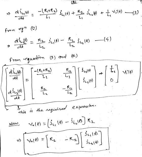
An RL circuit network is shown below in Figure 2. + Vri(t) W R1 vs(t) R2 Figure 2 RL circuir network 1. If the system input is the voltage of power source (t) and the system output is VRI(!) (voltage across RI), write the transfer function T/s) (Do not plug in any detail value) (10 point) Use R1-19, R2-122, L=1H and assume zero initial condition for all following questions, 2....
Please clear step by step and correct answers thumb
up
An RL circuit network is shown below in Figure 2. + Vri(t) W R1 vs(t) R2 Figure 2 RL circuir network 1. If the system input is the voltage of power source (t) and the system output is VRI(!) (voltage across RI), write the transfer function T/s) (Do not plug in any detail value) (10 point) Use R1-19, R2-122, L=1H and assume zero initial condition for all following questions, 2....
c) In estimating DC imperfections (input offset voltage, input offset current and the inverting amplifier with...
 c) In estimating DC imperfections (input offset voltage, input offset current and the inverting amplifier with nominal gain of -100 using 1 current) of an op-map, an and 10MQ resistors is implemented using the op-amp as shown in Fig 2(a) below R2 10MQ R 100k Vi Vo Figure 2(a): Inverting amplifier Measurements are conducted on the output voltage of the inverting amplifier under the following conditions: (i) the input (V) is open circuited and the output voltage is found to...
 1. Response of the RL circuit - After having been in position 1 for a long time, the switch in the circuit below is moved to position 2 at the time t = 0. Given that Vo = 12 V, R1 = 3092, R2 = 12092, R3 = 6022 and L = 0.2 H, determine; a) iz(0-) and vi(0-) b) iz(0) and vi(0) c) il(o) and vi(0) d) il(t) for t20 e) vi(t) for t20 RU AN
 The Natural Response of an RL Circuit In summary, to find the time constant of an RL circuit, find the Thevenin equivalent resistance se Learning Goal: To analyze an RL circuit to determine the initial current through an inductor, the time constant, and the expression for the natural response of the inductor current, and to use the expression for the inductor current to find other circuit quantities, such as current, voltage, power, or energy. The natural response of an RL...
 3. For the non-ideal buck converter in Fig. 3, 1) Derive the state space model with state variable vector X as (it, vc), input variable vector U as (vi, io), output variable vector Y as vo. Derive the coefficient matrices in the model below. Note that duty cycle should be considered and included. dt ) di di dt 2)Select the line of a L, ie., a L-4-i, +A2Mz + Bı'y4B12%.and use perturbation-and- dt linearization approach to derive its small-signal representation....
 The circuit
3-The circuit of problem # 2 is subjected to a small ac input by the signal generator. By neglecting the voltage drop across the coupling and bypass capacitors, determine the small signal voltage gain Vo/ Vì = Avi , input resistance Ri-vi / ii and the output resistance Ro external to R Avi= Ri= , Ro The accompanying circuit shows a 4-resistor biased JFET transistor Determine the values of Rp and Rs so that the Q-point is equal...
The circuit
3-The circuit of problem # 2 is subjected to a small ac input by the signal generator. By neglecting the voltage drop across the coupling and bypass capacitors, determine the small signal voltage gain Vo/ Vì = Avi , input resistance Ri-vi / ii and the output resistance Ro external to R Avi= Ri= , Ro The accompanying circuit shows a 4-resistor biased JFET transistor Determine the values of Rp and Rs so that the Q-point is equal...
 Q2. For the op-amp circuit as shown below, given that RS = 49.5 k, RL = 12 k 2, R1 = 10 kO, R2 = 9 ㏀, R3 = 7.5 ko, R4 = 5 ㏀R5 = 2.2 k2 Ry vo Ry Ri Rs (a) Determine the voltage gain G1-vo1/vs: Submit Answer Tries o/5 (b) Determine the voltage gain G2-vo/vs: Submit Answer Tries o/5 Q3. For the op-amp circuit shown below, find the value of VO, where R1 = 20 Ω,...
 Question 4. Refer to the circuit of Figure 4. R 802 50 uF с vi(t) v.(t) Figure 4 a) Draw the circuit in the Laplace domain, and then apply basic circuit theory in the Laplace domain to show that the Laplace transfer function H(s) defined for this system is: HS) V.(5) V (5) sta where a= RC [8 Marks] b) Use Laplace methods to determine the output voltage vo(t) when the input voltage is defined as: v (1) 40(1) The...
 Please answer clearly
Question 2 The amplifier shown in Figure 2 has the following parameters: Kn(W/L)-1 mA/V2, V-1 V Determine a) Voltage gain (Vo/vi) b) Input resistance (R) c) Output resistance (Ro) d) Maximum output voltage swing so as the amplifier stays in saturation mode. Assume VDD-20 V, R1-2.5 ΚΩ, R2-1KQ, R3-0.5 ΚΩ, R4-5 MQ, R5_1ΜΩ. R4 R1 R5 R2 Ro R3
Question 2 The amplifier shown in Figure 2 has the following parameters: Kn(W/L)-1 mA/V2, V-1 V Determine a)...
Please answer clearly
Question 2 The amplifier shown in Figure 2 has the following parameters: Kn(W/L)-1 mA/V2, V-1 V Determine a) Voltage gain (Vo/vi) b) Input resistance (R) c) Output resistance (Ro) d) Maximum output voltage swing so as the amplifier stays in saturation mode. Assume VDD-20 V, R1-2.5 ΚΩ, R2-1KQ, R3-0.5 ΚΩ, R4-5 MQ, R5_1ΜΩ. R4 R1 R5 R2 Ro R3
Question 2 The amplifier shown in Figure 2 has the following parameters: Kn(W/L)-1 mA/V2, V-1 V Determine a)...
 Find the output voltage Vo as an expression in terms of the input sources Vi, v2, v3, and the resistance R in the following op-amp circuit. 3. Ri Vy R: 4. In the following two stage op-amp circuit, find the output voltage Vo as an expression in terms of the input voltages v1, v2 and resistor values R1, R2, R3, and R4. R2 R ウー+
 Please clear step by step and correct answers thumb
up
An RL circuit network is shown below in Figure 2. + Vri(t) W R1 vs(t) R2 Figure 2 RL circuir network 1. If the system input is the voltage of power source (t) and the system output is VRI(!) (voltage across RI), write the transfer function T/s) (Do not plug in any detail value) (10 point) Use R1-19, R2-122, L=1H and assume zero initial condition for all following questions, 2....
Please clear step by step and correct answers thumb
up
An RL circuit network is shown below in Figure 2. + Vri(t) W R1 vs(t) R2 Figure 2 RL circuir network 1. If the system input is the voltage of power source (t) and the system output is VRI(!) (voltage across RI), write the transfer function T/s) (Do not plug in any detail value) (10 point) Use R1-19, R2-122, L=1H and assume zero initial condition for all following questions, 2....
 c) In estimating DC imperfections (input offset voltage, input offset current and the inverting amplifier with nominal gain of -100 using 1 current) of an op-map, an and 10MQ resistors is implemented using the op-amp as shown in Fig 2(a) below R2 10MQ R 100k Vi Vo Figure 2(a): Inverting amplifier Measurements are conducted on the output voltage of the inverting amplifier under the following conditions: (i) the input (V) is open circuited and the output voltage is found to...
Most questions answered within 3 hours.
-
In 20 words or less, what aspect of your degree course are you
passionate about? civil...
asked 2 minutes ago -
Learning Goal: To understand the relation between the strength
of an acid or a base and...
asked 3 minutes ago -
Discuss the role of integrated marketing communications
(IMC) in a firm’s overall marketing strategy? When executed...
asked 3 minutes ago -
(in Java) We wish to insert the following strings into a hash
table: BEN AL SUE...
asked 12 minutes ago -
Group think happens when the members of the group become more
interested in agreeing with each...
asked 11 minutes ago -
how might the HR Scorecard might be used to demonstrate value
creation that aligns with the...
asked 28 minutes ago -
If the racetrack publishes that the odds in favor of a horse
winning a race are...
asked 36 minutes ago -
2.
A particular sample of vinegar has a pH of 2.95.
Part A
If acetic acid...
asked 41 minutes ago -
1a.) A simple random sample of 100 Harvard undergraduates was
given a two-question astronomy test. 13%...
asked 46 minutes ago -
A spider hangs vertically from a thread of negligible mass. In
what situation, the tension in...
asked 47 minutes ago -
is an approach for addressing bottlenecks in a process or
system.
A. Utilization
B. Breakeven Analysis...
asked 1 hour ago -
A 125 g sample of an unknown substance is heated to 93.6 °C and
then dropped...
asked 1 hour ago