
Homework Answers

Add Answer to:
Consider the diagram in the quiver of one feedback unit of the transfer function G (s)...
A second-order process is described by its transfer function G(s) = (s+1)(843) and a PI controlle...
 A second-order process is described by its transfer function G(s) = (s+1)(843) and a PI controller by Consider feedback control with unit feedback gain as shown in Figure 1 A disturbance D(s) exists, and to achieve zero steady-state error, a small integral component is applied. Technical limitations restrict the controller gain kp to values of 0.2 or less. The goal is to examine the influence of the controller parameter k on the dynamic response. D(s) Controller Process X(s) Y(s) Figure...
Consider the unity feedback system is given below R(S) C(s) G(s) with transfer function: G() =...
 Consider the unity feedback system is given below R(S) C(s) G(s) with transfer function: G() = K(+2) s(s+ 1/s + 3)(+5) a) Sketch the root locus. Clearly indicate any asymptotes. b) Find the value of the gain K, that will make the system marginally stable. c) Find the value of the gain K, for which the closed-loop transfer function will have a pole on the real axis at (-0.5).
The open loop transfer function of a unity feedback system is 1. G(s)32 2s4 +5s3+s2 +2s...
 The open loop transfer function of a unity feedback system is 1. G(s)32 2s4 +5s3+s2 +2s Using Routh - Hurwitz criteria, (i) (ii) Determine the stability of the system. Find how many roots are lying in the left hand side and right hand side of the s-plane.
. (15 points) An unstable system can be stabilized by using negative feedback with a gain...
 . (15 points) An unstable system can be stabilized by using negative feedback with a gain K in the feedback loop. For instance, consider an unstable system with transfer function which has a pole in the right-hand s-plane, making the impulse response of the system h) grow as increases. Use negative feedback with a gain K> 0 in the feedback loop, and put H) in the forward loop. Draw a block diagram of the system. Obtain the transfer function Gus)...
03. (a) Consider the block diagram shown in Figure 3.1, and assume G(s)= 3. G,(s) and...
 03. (a) Consider the block diagram shown in Figure 3.1, and assume G(s)= 3. G,(s) and G,(s) 5+2 Y(s) R(S) G,() Gy(s) G;(s) Figure 3.1 3 (0) Y(s) Derive the system transfer function H(s)= of the system. Plot the R(s) poles and zeros of H(s) in the complex s-plane. State whether the system is stable or not stable, and why. [10 marks) (11) Obtain the impulse response of the system, that is ylt) for r(t)= 8(t). Evaluate the final value...
The open loop transfer function of an electro-mechanical system with unity feedback is: 24K G(s) S(s+2)(s +6) The Nyquist diagram of G(s) has a shape similar to the one shown below Nyquist diagram Cl...
 The open loop transfer function of an electro-mechanical system with unity feedback is: 24K G(s) S(s+2)(s +6) The Nyquist diagram of G(s) has a shape similar to the one shown below Nyquist diagram Cl When K -1, calculate both the frequency and the gain at which the plot crosses the real axis Hence state the gain margin or critical gain Kc for this system. If K is chosen as K-0.2Kc, show that the gain G(jo) l at a frequency ω-1.308...
Consider the unity feedback system is given below R(S) C(s) G() with transfer function: G(s) =...
 Consider the unity feedback system is given below R(S) C(s) G() with transfer function: G(s) = K s(s + 1)(s + 2)(8 + 6) a) Find the value of the gain K, that will make the system stable. b) Find the value of the gain K, that will make the system marginally stable. c) Find the actual location of the closed-loop poles when the system is marginally stable.
Consider the system shown as below. Draw a Bode diagram of the open-loop transfer function G(s).
 1 Consider the system shown as below. Draw a Bode diagram of the open-loop transfer function G(s). Determine the phase margin, gain-crossover frequency, gain margin and phase-crossover frequency, (Sketch the bode diagram by hand) 2 Consider the system shown as below. Use MATLAB to draw a bode diagram of the open-loop transfer function G(s). Show the gain-crossover frequency and phase-crossover frequency in the Bode diagram and determine the phase margin and gain margin. 3. Consider the system shown as below. Design a...
6) Consider the feedback system in Figure 1 with the loop transfer function a) [8 Marks]...
 6) Consider the feedback system in Figure 1 with the loop transfer function a) [8 Marks] Plot the Bode diagram for this loop transfer function b) 10 Marks] Determine the frequency at which the gain has unit magnitude and compute the phase angle at that frequency. Controller Process G(s)Y(s) Figure 1
2. The Nyquist diagram of a system's loop transfer function is shown in Figure 2. Assume...
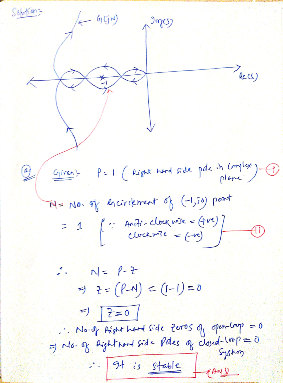
 2. The Nyquist diagram of a system's loop transfer function is shown in Figure 2. Assume that H(s) 1 and G(s) has no poles in the right half plane. Now suppose a gain K is cascaded with G(s) Find the range of positive K for which the system is stable. Im Re 18 0.5 Figure 2
 A second-order process is described by its transfer function G(s) = (s+1)(843) and a PI controller by Consider feedback control with unit feedback gain as shown in Figure 1 A disturbance D(s) exists, and to achieve zero steady-state error, a small integral component is applied. Technical limitations restrict the controller gain kp to values of 0.2 or less. The goal is to examine the influence of the controller parameter k on the dynamic response. D(s) Controller Process X(s) Y(s) Figure...
 Consider the unity feedback system is given below R(S) C(s) G(s) with transfer function: G() = K(+2) s(s+ 1/s + 3)(+5) a) Sketch the root locus. Clearly indicate any asymptotes. b) Find the value of the gain K, that will make the system marginally stable. c) Find the value of the gain K, for which the closed-loop transfer function will have a pole on the real axis at (-0.5).
 The open loop transfer function of a unity feedback system is 1. G(s)32 2s4 +5s3+s2 +2s Using Routh - Hurwitz criteria, (i) (ii) Determine the stability of the system. Find how many roots are lying in the left hand side and right hand side of the s-plane.
 . (15 points) An unstable system can be stabilized by using negative feedback with a gain K in the feedback loop. For instance, consider an unstable system with transfer function which has a pole in the right-hand s-plane, making the impulse response of the system h) grow as increases. Use negative feedback with a gain K> 0 in the feedback loop, and put H) in the forward loop. Draw a block diagram of the system. Obtain the transfer function Gus)...
 03. (a) Consider the block diagram shown in Figure 3.1, and assume G(s)= 3. G,(s) and G,(s) 5+2 Y(s) R(S) G,() Gy(s) G;(s) Figure 3.1 3 (0) Y(s) Derive the system transfer function H(s)= of the system. Plot the R(s) poles and zeros of H(s) in the complex s-plane. State whether the system is stable or not stable, and why. [10 marks) (11) Obtain the impulse response of the system, that is ylt) for r(t)= 8(t). Evaluate the final value...
 The open loop transfer function of an electro-mechanical system with unity feedback is: 24K G(s) S(s+2)(s +6) The Nyquist diagram of G(s) has a shape similar to the one shown below Nyquist diagram Cl When K -1, calculate both the frequency and the gain at which the plot crosses the real axis Hence state the gain margin or critical gain Kc for this system. If K is chosen as K-0.2Kc, show that the gain G(jo) l at a frequency ω-1.308...
 Consider the unity feedback system is given below R(S) C(s) G() with transfer function: G(s) = K s(s + 1)(s + 2)(8 + 6) a) Find the value of the gain K, that will make the system stable. b) Find the value of the gain K, that will make the system marginally stable. c) Find the actual location of the closed-loop poles when the system is marginally stable.
 6) Consider the feedback system in Figure 1 with the loop transfer function a) [8 Marks] Plot the Bode diagram for this loop transfer function b) 10 Marks] Determine the frequency at which the gain has unit magnitude and compute the phase angle at that frequency. Controller Process G(s)Y(s) Figure 1
 2. The Nyquist diagram of a system's loop transfer function is shown in Figure 2. Assume that H(s) 1 and G(s) has no poles in the right half plane. Now suppose a gain K is cascaded with G(s) Find the range of positive K for which the system is stable. Im Re 18 0.5 Figure 2
Most questions answered within 3 hours.
-
MATLAB
Part 1 – randFloatValue.m This function accepts two numbers,
lower and upper, and returns a...
asked 1 minute ago -
You have been asked to hide prizes around your house for your
3-year old nephew. His...
asked 3 minutes ago -
Ammonia will decompose into nitrogen and hydrogen at high
temperature. An industrial chemist studying this reaction...
asked 10 minutes ago -
10. Complete the table below
only using hexadecimal numbers:
AL CODE
EBX
EAX
[EAX]
mov eax,...
asked 27 minutes ago -
trust is best established through the combination of ------and
------- .
1. magnanimity and justice
2....
asked 42 minutes ago -
Blood pressure is normally taken on the upper arm at the level
of the heart. Suppose,...
asked 41 minutes ago -
Suppose that the satellite around the earth has an orbit that is
24 KM larger in...
asked 44 minutes ago -
Calculate the [OH (aq)] in limes which have a [H3O*(aq)] of 1.3 x
10 mol/L
asked 42 minutes ago -
A nozzle with a radius of 0.250 cm is attached to a garden hose
with a...
asked 54 minutes ago -
PLEASE do not use any loops for the program; only recursion is
allowed
4. Write a...
asked 1 hour ago -
Please help me with me. I did the first part to write the operations but in...
asked 1 hour ago -
Use Cryptool to find the Cryptographic SHA-1 hash value of the
string "abc". The calculator is...
asked 1 hour ago