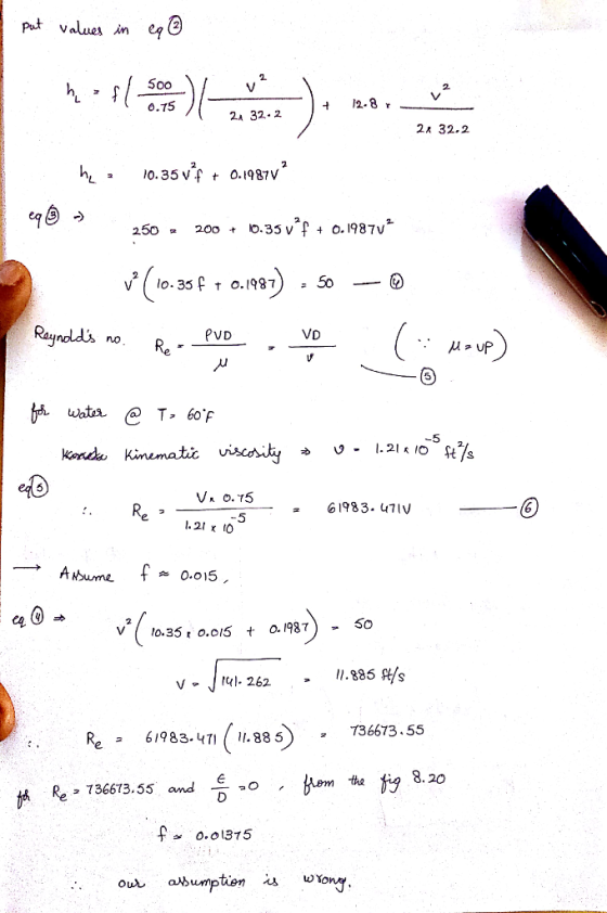
![The pump shown in Figure delivers a head of 250 ft to the water. One wants to determine the power that the pump adds to the water. The difference in elevation of the two ponds is 200 ft Assume Re 7.7 x 10⁵, Density is 1.94 slug/ft? and viscosity is 2.34x10%bs/ft2 a. State assumptions and setup Bernoulli equation between two reservoirs (5 b. Derive equation which relates friction factor, f and velocity from the above result (10 c. Derive Re in term of velocity [5] d. Calculate velocity, Re and friction factor via trial and error [15] e. Calculate major and minor losses [10) f. Calculate the pump power [5] Pump K,1.5 Lelbow 5.0 Pipe length 500 ft Pipe diameter 0.75 ft K, Lvalve Kn 0.8 Pipe roughness0 ent](http://img.homeworklib.com/questions/615f12c0-981c-11eb-aa7f-2726f5099a5c.png?x-oss-process=image/resize,w_560)
Fluid mechanics.
please answer all the questions.
Homework Answers


Add Answer to:
Fluid mechanics.
please answer all the questions.
The pump shown in Figure delivers a head of...
(Q1) The piping system shown here has a pump that delivers 10 hp to the fluid...
 (Q1) The piping system shown here has a pump that delivers 10 hp to the fluid ant a flow rate of 55 gpm of water at 80 F. Neglecting other losses, (a) evaluate the friction losses in the 272 ft-long discharge pipe and in the 12 ft- long suction pipe. (b) Calculate the pressure (psig) on top of the discharge tank. ...(25 marks) an 7 1.5 in Schedule 80 pipe 220 2 in Schedule 80 pipe
fluid mechanichs Previous Problem List Next (10 points) Pump K, =1.5 elbow Pipe length 500 ft...
 fluid mechanichs
Previous Problem List Next (10 points) Pump K, =1.5 elbow Pipe length 500 ft Pipe diameter: 0.75 ft Pipe roughness 0 The pump shown in the figure below delivers a head of 300 ft to the water Determine the power that the pump adds to the water The difference in elevation between the two ponds in 200 ft Answer tolerance-2% W, 252 736 hp 1 time Your overall recorded score is 0% You have 19 attempts remaining earch
fluid mechanichs
Previous Problem List Next (10 points) Pump K, =1.5 elbow Pipe length 500 ft Pipe diameter: 0.75 ft Pipe roughness 0 The pump shown in the figure below delivers a head of 300 ft to the water Determine the power that the pump adds to the water The difference in elevation between the two ponds in 200 ft Answer tolerance-2% W, 252 736 hp 1 time Your overall recorded score is 0% You have 19 attempts remaining earch
show all work will thunbs up Problem #7(30points! A motor- driven pump reservoir, through a 2500m long, 30 cm ID plastic level in the second re en centrifugal pump delivers 15°C water at the rate...
 show all work will thunbs up
Problem #7(30points! A motor- driven pump reservoir, through a 2500m long, 30 cm ID plastic level in the second re en centrifugal pump delivers 15°C water at the rate of 10m3/min from a pipe, to a second reservoir. The water servoir is 40 m above the water level in the first reservoir. The pump efficiency is 75%. The loss coefficient of the square-edged entrance is 0.5 a) Sketch the problem and locate your point...
show all work will thunbs up
Problem #7(30points! A motor- driven pump reservoir, through a 2500m long, 30 cm ID plastic level in the second re en centrifugal pump delivers 15°C water at the rate of 10m3/min from a pipe, to a second reservoir. The water servoir is 40 m above the water level in the first reservoir. The pump efficiency is 75%. The loss coefficient of the square-edged entrance is 0.5 a) Sketch the problem and locate your point...
solve both parts a and b please A centrifugal pump having a head capacity relationship given...
 solve both parts a and b please
A centrifugal pump having a head capacity relationship given by the equation; h = 160 - 9.58x10^Q? with hain feet when Q is in gpm, is to be used with a system similar to that shown in Figure 12.14. The fluid is water. Assume the pipe diameter to be 5-in, the total length of constant-diameter pipe is 700 ft, and the friction factor to be equal to 0.022. Neglect all minor losses. For...
solve both parts a and b please
A centrifugal pump having a head capacity relationship given by the equation; h = 160 - 9.58x10^Q? with hain feet when Q is in gpm, is to be used with a system similar to that shown in Figure 12.14. The fluid is water. Assume the pipe diameter to be 5-in, the total length of constant-diameter pipe is 700 ft, and the friction factor to be equal to 0.022. Neglect all minor losses. For...
[Problem 3] Two reservoirs are connected using the piping network shown in the figure. The pipes ...
 [Problem 3] Two reservoirs are connected using the piping network shown in the figure. The pipes are commercial steel. water is to be pumped using a pump (efficiency = 70%) that draws 8 kw of electric power from the mains. Ignore minor losses. Determine the flow rate through each pipe and the total flow between the reservoirs. Start with a friction factor of 0.02 for all pipes and use the Haaland equation to calculate updated friction factors. Ignore the length...
The water pump, as shown in the figure below, maintains a pressure of 6.5 psig at...
 The water pump, as shown in the figure below, maintains a
pressure of 6.5 psig at point 1. There is a filter, a half-open
disk valve, and two regular screwed elbows. There are 80 ft of
4-inch diameter commercial steel pipe. For water, take ρ = 1.94
slug/ft3 and μ = 2.09E−5 slug/ft⋅s. Take kvalve ≈ 2.8, kelbow ≈
0.64, kexit ≈ 1, and kvalve ≈ 0 (when the disk valve wide open). If
the flow rate is 0.55 ft3/s,...
The water pump, as shown in the figure below, maintains a
pressure of 6.5 psig at point 1. There is a filter, a half-open
disk valve, and two regular screwed elbows. There are 80 ft of
4-inch diameter commercial steel pipe. For water, take ρ = 1.94
slug/ft3 and μ = 2.09E−5 slug/ft⋅s. Take kvalve ≈ 2.8, kelbow ≈
0.64, kexit ≈ 1, and kvalve ≈ 0 (when the disk valve wide open). If
the flow rate is 0.55 ft3/s,...
4. The discharge pressure gauge reading is 5 lb/in2 (psi) for the pumping system shown in the ske...
 4. The discharge pressure gauge reading is 5 lb/in2 (psi) for the pumping system shown in the sketch below, with the outlet nozzle discharging a 2-inch diameter stream of water directly to the atmosphere. The gauge pressure at the pump suction inlet at the point of incipient cavitation is (-2,071.12) lb/ft, i.e., for vapor pressure of water at 68° F of 50.54 lb/ft2 absolute, and standard atmospheric pressure 30 in Hg. Friction losses in the suction piping from the reservoir...
Two reservoirs are connected using the piping network shown in the figure. The pipes are commerci...
 Two reservoirs are connected using the piping network shown in
the figure. The pipes are commercial steel. Water is to be pumped
using a pump (efficiency = 70%) that draws 8 kW of electric power
from the mains. Ignore minor losses. Determine the flow rate
through each pipe and the total flow between the reservoirs. Start
with a friction factor of 0.02 for all pipes and use the Haaland
equation to calculate updated friction factors. Ignore the length
of the...
Two reservoirs are connected using the piping network shown in
the figure. The pipes are commercial steel. Water is to be pumped
using a pump (efficiency = 70%) that draws 8 kW of electric power
from the mains. Ignore minor losses. Determine the flow rate
through each pipe and the total flow between the reservoirs. Start
with a friction factor of 0.02 for all pipes and use the Haaland
equation to calculate updated friction factors. Ignore the length
of the...
fluid mechanics SECTION A Petroleum distilate is pumped from one large diameter tank to another higher...
 fluid mechanics
SECTION A Petroleum distilate is pumped from one large diameter tank to another higher tank, via a pumping station in an oil refinery. The petroleum is pumped at a speed of 2 ms through a 150 m long pipeline of 100 mm internal diameter. The vertical distance pumped is 20 m. The sum of the entry, exit and other component losses is equivalent to 5 times the velocity head, Table Q1 Fluid density Friction factor f for the...
fluid mechanics
SECTION A Petroleum distilate is pumped from one large diameter tank to another higher tank, via a pumping station in an oil refinery. The petroleum is pumped at a speed of 2 ms through a 150 m long pipeline of 100 mm internal diameter. The vertical distance pumped is 20 m. The sum of the entry, exit and other component losses is equivalent to 5 times the velocity head, Table Q1 Fluid density Friction factor f for the...
Problem 3 A pipeline delivers water from Reservoir 1 to Reservoir 2 as shown in the following figure. The water levels at Reservoirs 1 and 2 are 50 ft and 20 ft, respectively. A globe valve is in...
 Problem 3 A pipeline delivers water from Reservoir 1 to Reservoir 2 as shown in the following figure. The water levels at Reservoirs 1 and 2 are 50 ft and 20 ft, respectively. A globe valve is installed in the pipeline with a minor head loss coefficient k 10. The pipe from Reservoir 1 to the globe valve is 1000 ft long and 6 inches in diameter. The pipe from the globe valve to Reservoir 2 is also 1000 ft...
 (Q1) The piping system shown here has a pump that delivers 10 hp to the fluid ant a flow rate of 55 gpm of water at 80 F. Neglecting other losses, (a) evaluate the friction losses in the 272 ft-long discharge pipe and in the 12 ft- long suction pipe. (b) Calculate the pressure (psig) on top of the discharge tank. ...(25 marks) an 7 1.5 in Schedule 80 pipe 220 2 in Schedule 80 pipe
 fluid mechanichs
Previous Problem List Next (10 points) Pump K, =1.5 elbow Pipe length 500 ft Pipe diameter: 0.75 ft Pipe roughness 0 The pump shown in the figure below delivers a head of 300 ft to the water Determine the power that the pump adds to the water The difference in elevation between the two ponds in 200 ft Answer tolerance-2% W, 252 736 hp 1 time Your overall recorded score is 0% You have 19 attempts remaining earch
fluid mechanichs
Previous Problem List Next (10 points) Pump K, =1.5 elbow Pipe length 500 ft Pipe diameter: 0.75 ft Pipe roughness 0 The pump shown in the figure below delivers a head of 300 ft to the water Determine the power that the pump adds to the water The difference in elevation between the two ponds in 200 ft Answer tolerance-2% W, 252 736 hp 1 time Your overall recorded score is 0% You have 19 attempts remaining earch
 show all work will thunbs up
Problem #7(30points! A motor- driven pump reservoir, through a 2500m long, 30 cm ID plastic level in the second re en centrifugal pump delivers 15°C water at the rate of 10m3/min from a pipe, to a second reservoir. The water servoir is 40 m above the water level in the first reservoir. The pump efficiency is 75%. The loss coefficient of the square-edged entrance is 0.5 a) Sketch the problem and locate your point...
show all work will thunbs up
Problem #7(30points! A motor- driven pump reservoir, through a 2500m long, 30 cm ID plastic level in the second re en centrifugal pump delivers 15°C water at the rate of 10m3/min from a pipe, to a second reservoir. The water servoir is 40 m above the water level in the first reservoir. The pump efficiency is 75%. The loss coefficient of the square-edged entrance is 0.5 a) Sketch the problem and locate your point...
 solve both parts a and b please
A centrifugal pump having a head capacity relationship given by the equation; h = 160 - 9.58x10^Q? with hain feet when Q is in gpm, is to be used with a system similar to that shown in Figure 12.14. The fluid is water. Assume the pipe diameter to be 5-in, the total length of constant-diameter pipe is 700 ft, and the friction factor to be equal to 0.022. Neglect all minor losses. For...
solve both parts a and b please
A centrifugal pump having a head capacity relationship given by the equation; h = 160 - 9.58x10^Q? with hain feet when Q is in gpm, is to be used with a system similar to that shown in Figure 12.14. The fluid is water. Assume the pipe diameter to be 5-in, the total length of constant-diameter pipe is 700 ft, and the friction factor to be equal to 0.022. Neglect all minor losses. For...
 [Problem 3] Two reservoirs are connected using the piping network shown in the figure. The pipes are commercial steel. water is to be pumped using a pump (efficiency = 70%) that draws 8 kw of electric power from the mains. Ignore minor losses. Determine the flow rate through each pipe and the total flow between the reservoirs. Start with a friction factor of 0.02 for all pipes and use the Haaland equation to calculate updated friction factors. Ignore the length...
 The water pump, as shown in the figure below, maintains a
pressure of 6.5 psig at point 1. There is a filter, a half-open
disk valve, and two regular screwed elbows. There are 80 ft of
4-inch diameter commercial steel pipe. For water, take ρ = 1.94
slug/ft3 and μ = 2.09E−5 slug/ft⋅s. Take kvalve ≈ 2.8, kelbow ≈
0.64, kexit ≈ 1, and kvalve ≈ 0 (when the disk valve wide open). If
the flow rate is 0.55 ft3/s,...
The water pump, as shown in the figure below, maintains a
pressure of 6.5 psig at point 1. There is a filter, a half-open
disk valve, and two regular screwed elbows. There are 80 ft of
4-inch diameter commercial steel pipe. For water, take ρ = 1.94
slug/ft3 and μ = 2.09E−5 slug/ft⋅s. Take kvalve ≈ 2.8, kelbow ≈
0.64, kexit ≈ 1, and kvalve ≈ 0 (when the disk valve wide open). If
the flow rate is 0.55 ft3/s,...
 4. The discharge pressure gauge reading is 5 lb/in2 (psi) for the pumping system shown in the sketch below, with the outlet nozzle discharging a 2-inch diameter stream of water directly to the atmosphere. The gauge pressure at the pump suction inlet at the point of incipient cavitation is (-2,071.12) lb/ft, i.e., for vapor pressure of water at 68° F of 50.54 lb/ft2 absolute, and standard atmospheric pressure 30 in Hg. Friction losses in the suction piping from the reservoir...
 Two reservoirs are connected using the piping network shown in
the figure. The pipes are commercial steel. Water is to be pumped
using a pump (efficiency = 70%) that draws 8 kW of electric power
from the mains. Ignore minor losses. Determine the flow rate
through each pipe and the total flow between the reservoirs. Start
with a friction factor of 0.02 for all pipes and use the Haaland
equation to calculate updated friction factors. Ignore the length
of the...
Two reservoirs are connected using the piping network shown in
the figure. The pipes are commercial steel. Water is to be pumped
using a pump (efficiency = 70%) that draws 8 kW of electric power
from the mains. Ignore minor losses. Determine the flow rate
through each pipe and the total flow between the reservoirs. Start
with a friction factor of 0.02 for all pipes and use the Haaland
equation to calculate updated friction factors. Ignore the length
of the...
 fluid mechanics
SECTION A Petroleum distilate is pumped from one large diameter tank to another higher tank, via a pumping station in an oil refinery. The petroleum is pumped at a speed of 2 ms through a 150 m long pipeline of 100 mm internal diameter. The vertical distance pumped is 20 m. The sum of the entry, exit and other component losses is equivalent to 5 times the velocity head, Table Q1 Fluid density Friction factor f for the...
fluid mechanics
SECTION A Petroleum distilate is pumped from one large diameter tank to another higher tank, via a pumping station in an oil refinery. The petroleum is pumped at a speed of 2 ms through a 150 m long pipeline of 100 mm internal diameter. The vertical distance pumped is 20 m. The sum of the entry, exit and other component losses is equivalent to 5 times the velocity head, Table Q1 Fluid density Friction factor f for the...
 Problem 3 A pipeline delivers water from Reservoir 1 to Reservoir 2 as shown in the following figure. The water levels at Reservoirs 1 and 2 are 50 ft and 20 ft, respectively. A globe valve is installed in the pipeline with a minor head loss coefficient k 10. The pipe from Reservoir 1 to the globe valve is 1000 ft long and 6 inches in diameter. The pipe from the globe valve to Reservoir 2 is also 1000 ft...
Most questions answered within 3 hours.
-
A magnetic dipole m(t) = m_0*cos(ωt) can be
described as current density j(r,t) = −cm(t) ×...
asked 3 minutes ago -
companies either hire outside programmers to
write_____ software or use their own internal developers.
asked 3 minutes ago -
Which food law was passed in 1996 and changed how pesticide
residues on food were regulated...
asked 4 minutes ago -
Probabilities and Counting. Yahtzee is a game that involves six
fair dice. When rolling all six...
asked 5 minutes ago -
What percent of revenue does net income represent for each
year?
Total Revenue
2017 = 60,319,000...
asked 26 minutes ago -
For Ti+2 (Z=22). Determine the correct ground state
& # of microstates. Use the correct tanabe...
asked 30 minutes ago -
Why did so many investment banks have to start buying CDO’s and
other mortgaged backed securities...
asked 45 minutes ago -
The mean cost of domestic airfares in the United States rose to
an all-time high of...
asked 56 minutes ago -
1.Magazine Luiza is a Brazilian retail chain for consumer
electronics. The company currently has 100 stores...
asked 54 minutes ago -
What is the molarity of ZnCl2 that forms when 25.0 g of zinc
completely reacts with...
asked 56 minutes ago -
For independent X and Y, we have probability density function
for them where pdf of X...
asked 1 hour ago -
The decomposition of SO2Cl2 is first order in SO2Cl2 and has a
rate constant of 1.42...
asked 1 hour ago