
Homework Answers

Add Answer to:
The input impedance Zi, the output impedance ZO and the voltage gain AV = (VO /...
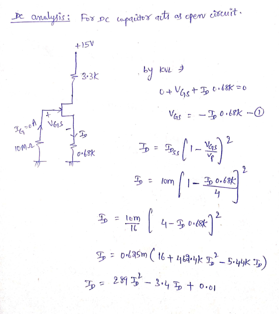
For the cascade amplifier of Figure Q1(a), determine the (1) transconductance factor, gm. a.c. diode resistance.,...
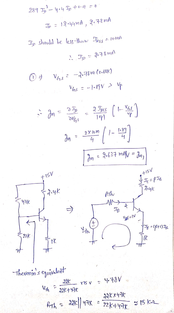
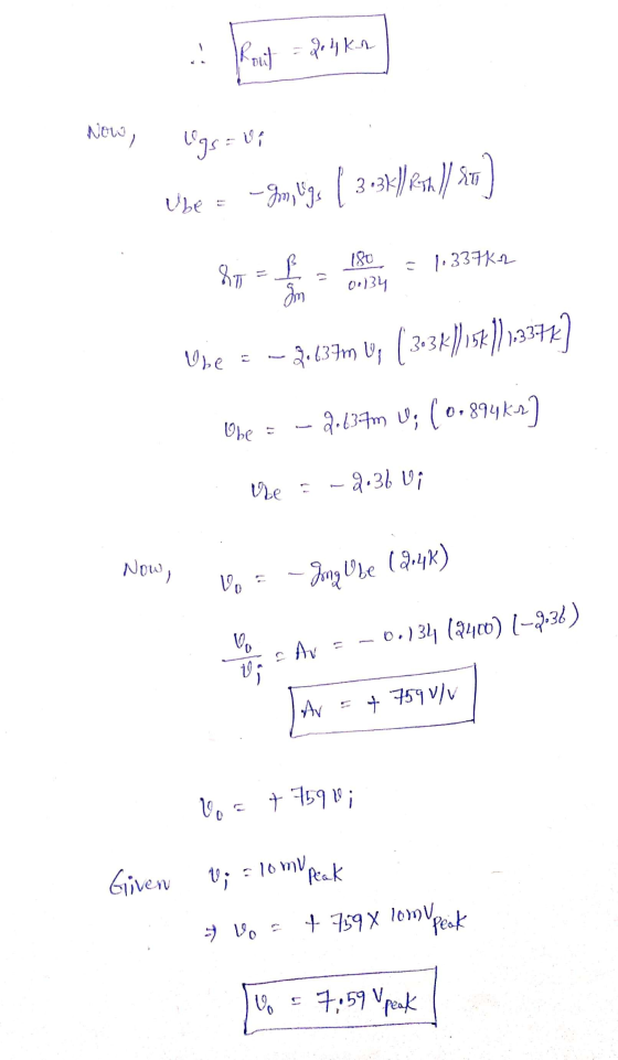
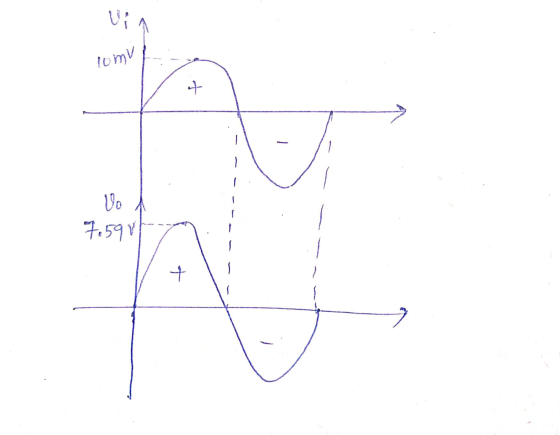
 For the cascade amplifier of Figure Q1(a), determine the (1) transconductance factor, gm. a.c. diode resistance., re. (iii) ac equivalent circuit (iv) input impedance, Z (v) output impedance, Z. (vi) voltage gain, Avi (vii) voltage gain, Av2. (viii) total cascade voltage gain, Avr. Given gm = 21 pss lvpl + 15 V Ipss - 10 mA Vp.4V Vase -- 1.5 V βος = 50 μs Γ. 40 ΚΩ RO 3.3 ΚΩ R81 22 ΚΩ Rc 10 ΚΩ O V. β...
(a) A voltage divider bypassed common-source (CS) FET amplifier biasing circuit with load R, is commonly...
 (a) A voltage divider bypassed common-source (CS) FET amplifier biasing circuit with load R, is commonly used in electronic circuit. (1) Design the circuit of a voltage divider bypassed common-source FET amplifier biasing circuit with load Ru. [4 marks) (ii) By referring to Q4(a)(i), design a bypassed common-source FET amplifier with biasing voltage-divider to meet the given specifications below: Supply voltage, Vcc = 12 V; Voltage gain, Ay = -10; Output load Ru = 10 kV2; input impedance Zi =...
Compute the voltage gain, input and output impedance for the following circuit if ß = 150...
 Compute the voltage gain, input and output impedance for the following circuit if ß = 150 and VBEQ = 0.7 V, VI = 26 mV. 4 + 10 V 40 ΚΩ R1 4 ΚΩ Ci CO Vs R2 VO 60 ΚΩ 5 ΚΩ RE R 1ΚΩ
(b) Compute the voltage gain, input and output impedance for the following circuit if ß =...
 (b) Compute the voltage gain, input and output impedance for the following circuit if ß = 150 and VBEQ = 0.7 V, V1 = 26 mV. A + 10 V 40 ΚΩ R1 4 ΚΩ Ci CO Vs R2 VO 60 ΚΩ 5 ΚΩ RE RL 1ΚΩ
3. In the amplifier circuit given below; Zi input impedance and circuit from input to output...
 3. In the amplifier circuit given below; Zi input
impedance and circuit from input to output Calculate the total
voltage gain [AV=(Vo/Vi)] which
is.
S-3) (20 Puan) Aşağıda verilen yükselteç devresinde; Zi giriş empedansını ve devrenin girişten çıkışa V olan toplam gerilim kazancını 4, = hesaplayınız. V +10 V R 10K R 10KOS Q Si B=100 R4 1ΚΩ Q6 Si B=100 r=o0 Vi R 15ΚΩ Si B=100 N Q3 Si B=100 RS 1202 Si B=100 Q5 Si B=100 3,6ΚΩΣ RE...
3. In the amplifier circuit given below; Zi input
impedance and circuit from input to output Calculate the total
voltage gain [AV=(Vo/Vi)] which
is.
S-3) (20 Puan) Aşağıda verilen yükselteç devresinde; Zi giriş empedansını ve devrenin girişten çıkışa V olan toplam gerilim kazancını 4, = hesaplayınız. V +10 V R 10K R 10KOS Q Si B=100 R4 1ΚΩ Q6 Si B=100 r=o0 Vi R 15ΚΩ Si B=100 N Q3 Si B=100 RS 1202 Si B=100 Q5 Si B=100 3,6ΚΩΣ RE...
Using the circuit of Figure 2, calculate the output voltage Vo) using five different input voltages...
 Using the circuit of Figure 2, calculate the output voltage Vo) using five different input voltages (Vm) between 0 and 15V. Record your answers in Table Calculate the proportionality constant (k) that relates the output voltage to the input voltage as follows, k=-out Vin 10 kΩ 10kg2 10 k2 10 kΩ
Please select the correct statements: The bandwidth of a circuit can be found by measuring the 5/7 drop in output signal The input impedance of a circuit can be found by adding a resistor in parallel...
 Please select the correct statements: The bandwidth of a circuit can be found by measuring the 5/7 drop in output signal The input impedance of a circuit can be found by adding a resistor in parallel and measuring the change in voltage The X-Y mode on the scope shows the phase difference and distortion between two inputs E12 resistors have +/-10% tolerence. Typical values are: 100, 1k, 1.5k, 2k Ohm An voltage follower op-amp with a slew rate of 1V/ms...
BJT and Amplifier Circuits +15 V 27 k R2 680 Ω Compute: 53 1. Show the extra units and connections RE 680 2 R2 12 kC2 2. The input and the output impedance 3. The Voltage gain Av 4. If the input...
 BJT and Amplifier Circuits +15 V 27 k R2 680 Ω Compute: 53 1. Show the extra units and connections RE 680 2 R2 12 kC2 2. The input and the output impedance 3. The Voltage gain Av 4. If the input ac voltage with Vp-1 mV, draw the output voltage. What is the maximum vin value. 5. 6. The current gain Ai and Ap. 7. Compute the produced power and the consumed power in transistor and RL.
BJT and...
BJT and Amplifier Circuits +15 V 27 k R2 680 Ω Compute: 53 1. Show the extra units and connections RE 680 2 R2 12 kC2 2. The input and the output impedance 3. The Voltage gain Av 4. If the input ac voltage with Vp-1 mV, draw the output voltage. What is the maximum vin value. 5. 6. The current gain Ai and Ap. 7. Compute the produced power and the consumed power in transistor and RL.
BJT and...
Assuming an ideal op-amp in the following circuit, find output voltage, Vo if R1= 2 K2,...
 Assuming an ideal op-amp in the following circuit, find output voltage, Vo if R1= 2 K2, R2=8 K2, R3=5.1 K2, R4=6 KN, R5=14 KN, R6=4.2 KS, RL=10.3 KS, V1=1V, 12=0.5 mA and V3=3.2 V. R6 R1 R5 Vo w + * RL + 12 R2 V1 R3 R4 V3 Answer: OV Using the above circuit, but consider the following component values: R1= 2 K12 R2=8 K2, R3=2.9 K2, R4=6 KI2, R5=10.8 K92, R6=15 KO, RL=10 K2, V1=1V, 12=0.5mA and V3=2V....
Assuming an ideal op-amp in the following circuit, find output voltage, Vo if R1= 2 K12,...
 Assuming an ideal op-amp in the following circuit, find output voltage, Vo if R1= 2 K12, R2=8 KN, R3=3.9 KN, R4=6 KN, R5=18 K2, R6=4.4 KN, RL=12.5 KN, V1=1V, 12=0.5 mA and V3=3.4 V. R6 R1 R5 Vo + + RL R2 V1 R3 R4 + V3 Answer: LOV Using the above circuit, but consider the following component values: R1= 2 KO2 R2=8 K12, R3=3.6 K12, R4=6 K12, R5=16.9 KN, R6=15 KN, RL=10 KO, V1=1V, 12=0.5mA and V3=2V. What is...
 For the cascade amplifier of Figure Q1(a), determine the (1) transconductance factor, gm. a.c. diode resistance., re. (iii) ac equivalent circuit (iv) input impedance, Z (v) output impedance, Z. (vi) voltage gain, Avi (vii) voltage gain, Av2. (viii) total cascade voltage gain, Avr. Given gm = 21 pss lvpl + 15 V Ipss - 10 mA Vp.4V Vase -- 1.5 V βος = 50 μs Γ. 40 ΚΩ RO 3.3 ΚΩ R81 22 ΚΩ Rc 10 ΚΩ O V. β...
 (a) A voltage divider bypassed common-source (CS) FET amplifier biasing circuit with load R, is commonly used in electronic circuit. (1) Design the circuit of a voltage divider bypassed common-source FET amplifier biasing circuit with load Ru. [4 marks) (ii) By referring to Q4(a)(i), design a bypassed common-source FET amplifier with biasing voltage-divider to meet the given specifications below: Supply voltage, Vcc = 12 V; Voltage gain, Ay = -10; Output load Ru = 10 kV2; input impedance Zi =...
 Compute the voltage gain, input and output impedance for the following circuit if ß = 150 and VBEQ = 0.7 V, VI = 26 mV. 4 + 10 V 40 ΚΩ R1 4 ΚΩ Ci CO Vs R2 VO 60 ΚΩ 5 ΚΩ RE R 1ΚΩ
 (b) Compute the voltage gain, input and output impedance for the following circuit if ß = 150 and VBEQ = 0.7 V, V1 = 26 mV. A + 10 V 40 ΚΩ R1 4 ΚΩ Ci CO Vs R2 VO 60 ΚΩ 5 ΚΩ RE RL 1ΚΩ
 3. In the amplifier circuit given below; Zi input
impedance and circuit from input to output Calculate the total
voltage gain [AV=(Vo/Vi)] which
is.
S-3) (20 Puan) Aşağıda verilen yükselteç devresinde; Zi giriş empedansını ve devrenin girişten çıkışa V olan toplam gerilim kazancını 4, = hesaplayınız. V +10 V R 10K R 10KOS Q Si B=100 R4 1ΚΩ Q6 Si B=100 r=o0 Vi R 15ΚΩ Si B=100 N Q3 Si B=100 RS 1202 Si B=100 Q5 Si B=100 3,6ΚΩΣ RE...
3. In the amplifier circuit given below; Zi input
impedance and circuit from input to output Calculate the total
voltage gain [AV=(Vo/Vi)] which
is.
S-3) (20 Puan) Aşağıda verilen yükselteç devresinde; Zi giriş empedansını ve devrenin girişten çıkışa V olan toplam gerilim kazancını 4, = hesaplayınız. V +10 V R 10K R 10KOS Q Si B=100 R4 1ΚΩ Q6 Si B=100 r=o0 Vi R 15ΚΩ Si B=100 N Q3 Si B=100 RS 1202 Si B=100 Q5 Si B=100 3,6ΚΩΣ RE...
 Using the circuit of Figure 2, calculate the output voltage Vo) using five different input voltages (Vm) between 0 and 15V. Record your answers in Table Calculate the proportionality constant (k) that relates the output voltage to the input voltage as follows, k=-out Vin 10 kΩ 10kg2 10 k2 10 kΩ
 Please select the correct statements: The bandwidth of a circuit can be found by measuring the 5/7 drop in output signal The input impedance of a circuit can be found by adding a resistor in parallel and measuring the change in voltage The X-Y mode on the scope shows the phase difference and distortion between two inputs E12 resistors have +/-10% tolerence. Typical values are: 100, 1k, 1.5k, 2k Ohm An voltage follower op-amp with a slew rate of 1V/ms...
 BJT and Amplifier Circuits +15 V 27 k R2 680 Ω Compute: 53 1. Show the extra units and connections RE 680 2 R2 12 kC2 2. The input and the output impedance 3. The Voltage gain Av 4. If the input ac voltage with Vp-1 mV, draw the output voltage. What is the maximum vin value. 5. 6. The current gain Ai and Ap. 7. Compute the produced power and the consumed power in transistor and RL.
BJT and...
BJT and Amplifier Circuits +15 V 27 k R2 680 Ω Compute: 53 1. Show the extra units and connections RE 680 2 R2 12 kC2 2. The input and the output impedance 3. The Voltage gain Av 4. If the input ac voltage with Vp-1 mV, draw the output voltage. What is the maximum vin value. 5. 6. The current gain Ai and Ap. 7. Compute the produced power and the consumed power in transistor and RL.
BJT and...
 Assuming an ideal op-amp in the following circuit, find output voltage, Vo if R1= 2 K2, R2=8 K2, R3=5.1 K2, R4=6 KN, R5=14 KN, R6=4.2 KS, RL=10.3 KS, V1=1V, 12=0.5 mA and V3=3.2 V. R6 R1 R5 Vo w + * RL + 12 R2 V1 R3 R4 V3 Answer: OV Using the above circuit, but consider the following component values: R1= 2 K12 R2=8 K2, R3=2.9 K2, R4=6 KI2, R5=10.8 K92, R6=15 KO, RL=10 K2, V1=1V, 12=0.5mA and V3=2V....
 Assuming an ideal op-amp in the following circuit, find output voltage, Vo if R1= 2 K12, R2=8 KN, R3=3.9 KN, R4=6 KN, R5=18 K2, R6=4.4 KN, RL=12.5 KN, V1=1V, 12=0.5 mA and V3=3.4 V. R6 R1 R5 Vo + + RL R2 V1 R3 R4 + V3 Answer: LOV Using the above circuit, but consider the following component values: R1= 2 KO2 R2=8 K12, R3=3.6 K12, R4=6 K12, R5=16.9 KN, R6=15 KN, RL=10 KO, V1=1V, 12=0.5mA and V3=2V. What is...
Most questions answered within 3 hours.
-
3) What are the typical social structures in a global city?
asked 1 hour ago -
Luther Corporation
Consolidated Balance Sheet
December 31, 2019 and 2018 (in $ millions)
Assets
2019
2018...
asked 1 hour ago -
(Expected rate of return and risk) Carter Inc. is evaluating a
security. Calculate the investment’s expected...
asked 3 hours ago -
What specific indicators can point to lack of progress for
African Americans in American society?
asked 4 hours ago -
1-The Electrons in a beam are moving at 2.7×10⁸ m/s in an
electric field of 15000...
asked 5 hours ago -
A gas tank is a vertical cylinder. It has a radius of 1m, a
height of...
asked 5 hours ago -
Accent Software faces the following conditions. All of these
support Accent’s use of a market-penetration pricing...
asked 6 hours ago -
A mathematically inclined friend emails you the following
instructions: "Meet me in the cafeteria the first...
asked 6 hours ago -
A monopoly sells in two countries . The demand curves in the two
countries are p1...
asked 7 hours ago -
A .15kg rubber ball is bounced off a wall. Before hitting the
wall, the ball moves...
asked 8 hours ago -
A manufacturing company preparing to build a new plant is
considering three potential locations for it....
asked 8 hours ago -
B. If compound Y has approximately the same values of solubility
in toluene as compound X,...
asked 9 hours ago