
Homework Answers


Add Answer to:
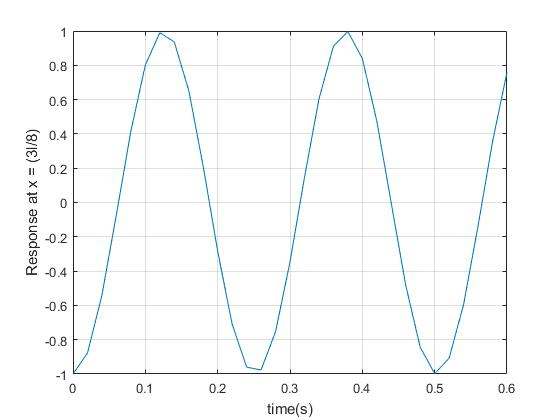
The displacement of point P on a clamped-clamped cable is shown in Figure (1), below, when...
Determine magnitude of the electric field at the point P shown in the figure(Figure 1) ....
Determine magnitude of the electric field at the point P shown in the figure(Figure 1) . The two charges are separated by a distance of 2a. Point P is on the perpendicular bisector of the line joining the charges, a distance x from the midpoint between them.Determine the direction of the electric field. Assume that the positive x and y axes are directed to the right and upward respectively.
As shown in the figure below, a uniform beam is supported by a cable at one...
 As shown in the figure below, a uniform beam is supported by a cable at one end and the force of friction at the other end. The cable makes an angle of 0 = 30°, the length of the beam is L = 3.75 m, the coefficient of static friction between the wall and the beam is Ms = 0.520, and the weight of the beam is represented by w. Determine the minimum distance x from point A at which...
As shown in the figure below, a uniform beam is supported by a cable at one...
 As shown in the figure below, a uniform beam is supported by a
cable at one end and the force of friction at the other end. The
cable makes an angle of θ = 30°,the length of the beam is L= 4.00
m, the coefficient of static friction between the wall and the beam
is μs = 0.500, and the weight of the beam is represented
by w. Determine the minimum distance x from point
A at which an additional...
As shown in the figure below, a uniform beam is supported by a
cable at one end and the force of friction at the other end. The
cable makes an angle of θ = 30°,the length of the beam is L= 4.00
m, the coefficient of static friction between the wall and the beam
is μs = 0.500, and the weight of the beam is represented
by w. Determine the minimum distance x from point
A at which an additional...
As shown in the figure below, a uniform beam is supported by a cable at one...
As shown in the figure below, a uniform beam is supported by a cable at one end and the force of friction at the other end. The cable makes an angle of θ = 30°, the length of the beam is L = 4.25 m, the coefficient of static friction between the wall and the beam is μs = 0.420, and the weight of the beam is represented by w. Determine the minimum distance x from point A at which...
The beam shown (Figure 1) is supported by a pin at A and a cable at...
 The beam shown (Figure 1) is
supported by a pin at A and a cable at B. Two
loads P = 13 kN are applied straight down from the
centerline of the bottom face. Determine the state of stress at the
point shown (Figure 2) in a section 2 m from the wall. The
dimensions are w = 5.2 cm , h = 10.5 cm ,
L = 0.8 m , a = 1.5 cm , and b = 4...
The beam shown (Figure 1) is
supported by a pin at A and a cable at B. Two
loads P = 13 kN are applied straight down from the
centerline of the bottom face. Determine the state of stress at the
point shown (Figure 2) in a section 2 m from the wall. The
dimensions are w = 5.2 cm , h = 10.5 cm ,
L = 0.8 m , a = 1.5 cm , and b = 4...
The beam shown (Figure 1) is supported by a pin at A and a cable at...
 The beam shown (Figure 1) is supported by a pin at A
and a cable at B. Two loads P = 13 kN are applied
straight down from the centerline of the bottom face. Determine the
state of stress at the point shown (Figure 2) in a section 2 m from
the wall. The dimensions are w = 5.2 cm , h =
10.5 cm , L = 0.8 m , a = 1.5 cm , and b
= 4...
The beam shown (Figure 1) is supported by a pin at A
and a cable at B. Two loads P = 13 kN are applied
straight down from the centerline of the bottom face. Determine the
state of stress at the point shown (Figure 2) in a section 2 m from
the wall. The dimensions are w = 5.2 cm , h =
10.5 cm , L = 0.8 m , a = 1.5 cm , and b
= 4...
The beam shown (Figure 1) is supported by a pin at A and a cable at...
 The beam shown (Figure 1) is supported by a pin at A and a cable at
B. Two loads P = 13 kN are applied straight down
from the centerline of the bottom face. Determine the state of
stress at the point shown (Figure 2) in a section 2 m from the
wall. The dimensions are w = 5.2 cm , h = 10.5 cm
, L = 0.8 m , a = 1.5 cm , and b = 4...
The beam shown (Figure 1) is supported by a pin at A and a cable at
B. Two loads P = 13 kN are applied straight down
from the centerline of the bottom face. Determine the state of
stress at the point shown (Figure 2) in a section 2 m from the
wall. The dimensions are w = 5.2 cm , h = 10.5 cm
, L = 0.8 m , a = 1.5 cm , and b = 4...
Please write (x,y) point for each point on the x-axis. ( P 3.11 3 of 10...
 Please write (x,y) point for each point on the x-axis. (
P 3.11 3 of 10 I Revie Plot the points for the energy versus time that are separated by the step At = 0.5 ms. The current through a 0.5 F capacitor is shown in the figure. Al t = 0, the voltage is zero. (Figure 1) +40 wt) stored energy vs time w(t) stored energy vs time Points 1 x 0.0 y: 0.00 2 x 0.5 0.20 y....
Please write (x,y) point for each point on the x-axis. (
P 3.11 3 of 10 I Revie Plot the points for the energy versus time that are separated by the step At = 0.5 ms. The current through a 0.5 F capacitor is shown in the figure. Al t = 0, the voltage is zero. (Figure 1) +40 wt) stored energy vs time w(t) stored energy vs time Points 1 x 0.0 y: 0.00 2 x 0.5 0.20 y....
The cable supports the loading shown in (Figure 1). Part A Determine the magnitude of the...
 The cable supports the loading shown in (Figure 1). Part A Determine the magnitude of the horizontal force P so that XB = 8 m. Express your answer to three significant figures and include the appropriate units. uÀ ? P= Value Units Submit Previous Answers Request Answer Figure 1 of 1 X Incorrect; Try Again; 4 attempts remaining XB 4 m B < Return to Assignment Provide Feedback P 6 m 1 1 m 600 N D 1 -2 m-
The figure below is a cross-sectional view of a convial cable. The center conductor is surrounded...
 The figure below is a cross-sectional view of a convial cable. The center conductor is surrounded by a rubber layer, an outer conductor, and another rubber layer. In a particular application, the current in the inner conductor is 11 - 1.12 A out of the page and the current in the outer conductor is 3.18 A into the page. Assuming the distance de 100 m, answer the following (a) Determine the magnitude and direction of the magnetic field at point...
 As shown in the figure below, a uniform beam is supported by a cable at one end and the force of friction at the other end. The cable makes an angle of 0 = 30°, the length of the beam is L = 3.75 m, the coefficient of static friction between the wall and the beam is Ms = 0.520, and the weight of the beam is represented by w. Determine the minimum distance x from point A at which...
 As shown in the figure below, a uniform beam is supported by a
cable at one end and the force of friction at the other end. The
cable makes an angle of θ = 30°,the length of the beam is L= 4.00
m, the coefficient of static friction between the wall and the beam
is μs = 0.500, and the weight of the beam is represented
by w. Determine the minimum distance x from point
A at which an additional...
As shown in the figure below, a uniform beam is supported by a
cable at one end and the force of friction at the other end. The
cable makes an angle of θ = 30°,the length of the beam is L= 4.00
m, the coefficient of static friction between the wall and the beam
is μs = 0.500, and the weight of the beam is represented
by w. Determine the minimum distance x from point
A at which an additional...
 The beam shown (Figure 1) is
supported by a pin at A and a cable at B. Two
loads P = 13 kN are applied straight down from the
centerline of the bottom face. Determine the state of stress at the
point shown (Figure 2) in a section 2 m from the wall. The
dimensions are w = 5.2 cm , h = 10.5 cm ,
L = 0.8 m , a = 1.5 cm , and b = 4...
The beam shown (Figure 1) is
supported by a pin at A and a cable at B. Two
loads P = 13 kN are applied straight down from the
centerline of the bottom face. Determine the state of stress at the
point shown (Figure 2) in a section 2 m from the wall. The
dimensions are w = 5.2 cm , h = 10.5 cm ,
L = 0.8 m , a = 1.5 cm , and b = 4...
 The beam shown (Figure 1) is supported by a pin at A
and a cable at B. Two loads P = 13 kN are applied
straight down from the centerline of the bottom face. Determine the
state of stress at the point shown (Figure 2) in a section 2 m from
the wall. The dimensions are w = 5.2 cm , h =
10.5 cm , L = 0.8 m , a = 1.5 cm , and b
= 4...
The beam shown (Figure 1) is supported by a pin at A
and a cable at B. Two loads P = 13 kN are applied
straight down from the centerline of the bottom face. Determine the
state of stress at the point shown (Figure 2) in a section 2 m from
the wall. The dimensions are w = 5.2 cm , h =
10.5 cm , L = 0.8 m , a = 1.5 cm , and b
= 4...
 The beam shown (Figure 1) is supported by a pin at A and a cable at
B. Two loads P = 13 kN are applied straight down
from the centerline of the bottom face. Determine the state of
stress at the point shown (Figure 2) in a section 2 m from the
wall. The dimensions are w = 5.2 cm , h = 10.5 cm
, L = 0.8 m , a = 1.5 cm , and b = 4...
The beam shown (Figure 1) is supported by a pin at A and a cable at
B. Two loads P = 13 kN are applied straight down
from the centerline of the bottom face. Determine the state of
stress at the point shown (Figure 2) in a section 2 m from the
wall. The dimensions are w = 5.2 cm , h = 10.5 cm
, L = 0.8 m , a = 1.5 cm , and b = 4...
 Please write (x,y) point for each point on the x-axis. (
P 3.11 3 of 10 I Revie Plot the points for the energy versus time that are separated by the step At = 0.5 ms. The current through a 0.5 F capacitor is shown in the figure. Al t = 0, the voltage is zero. (Figure 1) +40 wt) stored energy vs time w(t) stored energy vs time Points 1 x 0.0 y: 0.00 2 x 0.5 0.20 y....
Please write (x,y) point for each point on the x-axis. (
P 3.11 3 of 10 I Revie Plot the points for the energy versus time that are separated by the step At = 0.5 ms. The current through a 0.5 F capacitor is shown in the figure. Al t = 0, the voltage is zero. (Figure 1) +40 wt) stored energy vs time w(t) stored energy vs time Points 1 x 0.0 y: 0.00 2 x 0.5 0.20 y....
 The cable supports the loading shown in (Figure 1). Part A Determine the magnitude of the horizontal force P so that XB = 8 m. Express your answer to three significant figures and include the appropriate units. uÀ ? P= Value Units Submit Previous Answers Request Answer Figure 1 of 1 X Incorrect; Try Again; 4 attempts remaining XB 4 m B < Return to Assignment Provide Feedback P 6 m 1 1 m 600 N D 1 -2 m-
 The figure below is a cross-sectional view of a convial cable. The center conductor is surrounded by a rubber layer, an outer conductor, and another rubber layer. In a particular application, the current in the inner conductor is 11 - 1.12 A out of the page and the current in the outer conductor is 3.18 A into the page. Assuming the distance de 100 m, answer the following (a) Determine the magnitude and direction of the magnetic field at point...
Most questions answered within 3 hours.
-
1. Which of the following is NOT an argument that McMahan uses
to show that jus...
asked 16 minutes ago -
A crate slides up a frictionless slope. At the end of 3 seconds
its velocity is...
asked 33 minutes ago -
Use the following information to answer the next seven
questions.
Suppose there are three potential states...
asked 29 minutes ago -
If we only have interstitial and substitutional diffusion, then
what do we consider the process of...
asked 45 minutes ago -
You look at yourself in a shiny 9.6-cm-diameter Christmas tree
ball.
If your face is 21.0...
asked 47 minutes ago -
If we were to measure the relaxation time of a muscle after
undergoing tetanus compared to...
asked 46 minutes ago -
4CO(g) + 8H2(g) -----> 3CH4(g) +
CO2(g) + 2H2O(l)
Use the following data as needed to...
asked 49 minutes ago -
without using map
1. Write a C++ program to find out the top 10 words in...
asked 1 hour ago -
1)Calculate the percent ionization of a
0.330 M solution of hypochlorous
acid.
% Ionization = %...
asked 1 hour ago -
1a) How many grams of K2SO4 are in 250mL
of 0.11 M K2SO4 solution?
_____ g...
asked 56 minutes ago -
The vapor pressure of a solution containing 38.7 g glycerin
(C3H8O3) in 146.2 g ethanol (C2H5OH)...
asked 1 hour ago -
A physics major is cooking breakfast when he notices that the
frictional force between the steel...
asked 1 hour ago