![Write a small report of maximum one page answering the following questions: [8 marks] (a) What is apparent power? (b) What is](http://img.homeworklib.com/questions/e4611780-a30d-11eb-84a3-b9d6f57c47c0.png?x-oss-process=image/resize,w_560)

Homework Answers
1.


for any doubt feel free to ask.
Add Answer to:
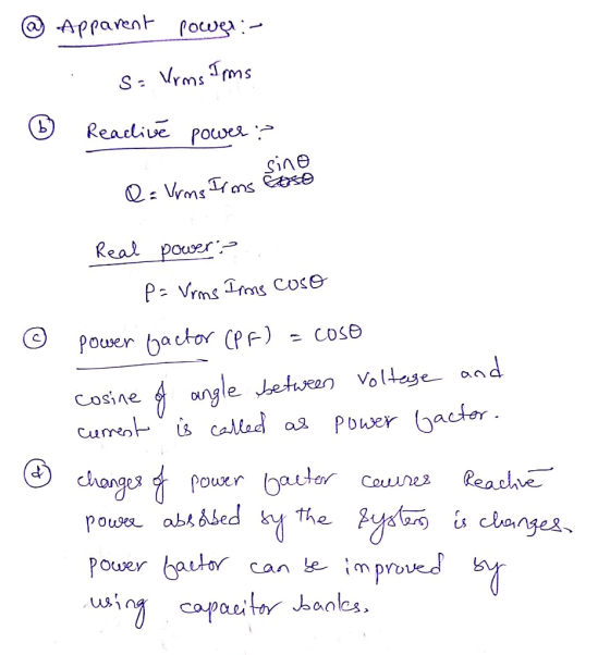
Write a small report of maximum one page answering the following questions: [8 marks] (a) What...
(a) For the circuit of Figure 4, assuming a sinusoidal is(t) (0) Prove that the resonant frequeney is given by o- (3 marks) LC (ii) If the total admittance at resonance is 20 ms (seen by the source)...
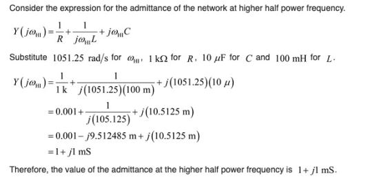
 (a) For the circuit of Figure 4, assuming a sinusoidal is(t) (0) Prove that the resonant frequeney is given by o- (3 marks) LC (ii) If the total admittance at resonance is 20 ms (seen by the source) with resonant frequency of wo 5000 rad/s and quality factor of Q-10, calculate the values of R L, C, the bandwidth and half-power frequencies in Hertz. (4 marks) VG and hence show (iii) Derive an expression for the driving point impedance Z(jø)...
Please provide step by step solution with all formulas. Q1. A series RLC circuit as shown...
 Please provide step by step solution with all formulas.
Q1. A series RLC circuit as shown in Figure Q1 has a resonant frequency,o, of 200t rad/s, inductance, L = 50 mH and the quality factor, Q = 15, and it is driven by a voltage source, Vin(t) = 220sin(ot) R L m Vin(t) с Figure Q1 Calculate: (a) The value of R and C. [4] [6] [4] (b) The energy stored, the average power and the energy dissipated per cycle....
Please provide step by step solution with all formulas.
Q1. A series RLC circuit as shown in Figure Q1 has a resonant frequency,o, of 200t rad/s, inductance, L = 50 mH and the quality factor, Q = 15, and it is driven by a voltage source, Vin(t) = 220sin(ot) R L m Vin(t) с Figure Q1 Calculate: (a) The value of R and C. [4] [6] [4] (b) The energy stored, the average power and the energy dissipated per cycle....
51 For the low pass filter in figure 5 find: [2 Marks] Cutoff(Critical) frequency Output Voltage...
 51 For the low pass filter in figure 5 find: [2 Marks] Cutoff(Critical) frequency Output Voltage at Cut off frequency 4.7 k C 1020 V 10 F Figure 5 6 Find at resonance from figure 5: [3 Marks] a. Resonant Frequency. d. Quality factor. e. Bandwidth b. Impedance at resonance f. Current at the half power Current at resonance. c. Vs 10 v L-1mH C-10uF R-102 C L R V Figure 5
need help graphing this to make it a "voltage across the resistor vs. frequency" please show...
 need help graphing this to make it a "voltage across the
resistor vs. frequency" please show work thank you
how is it in complete?
EXPERIMENT 7. RLC SERIES CIRCUIT NAN PART DATE 3/ylis LA ROCEDURE A: REACTANCES AND POTENTIALs Resistance of inductor R Resistance of L & N box Capacitance of Cenco box Power Supply Voltage from DMNM Voltage across the capacitor V 500 0.10 3.00 S2 volts volts Voltage across the inductor V evots Voltage across L & N...
need help graphing this to make it a "voltage across the
resistor vs. frequency" please show work thank you
how is it in complete?
EXPERIMENT 7. RLC SERIES CIRCUIT NAN PART DATE 3/ylis LA ROCEDURE A: REACTANCES AND POTENTIALs Resistance of inductor R Resistance of L & N box Capacitance of Cenco box Power Supply Voltage from DMNM Voltage across the capacitor V 500 0.10 3.00 S2 volts volts Voltage across the inductor V evots Voltage across L & N...
1.6 load not in a three phase system) is rated at 50 KVA with a power...
 1.6 load not in a three phase system) is rated at 50 KVA with a power factor of 0.8 lagging. A what is the power factor angle? 1.7. For a balanced three phase system, if the wye connected load has impedance 50+20j, determine the total (a single load, complex power of the load if 120225° V rms (ignore the line impedance). 1.8 An ideal transformer has a tuns ratio (N2/NI) of 6, if the magnitude of the primary port (port...
Solve the question A-1,2,3 & B please. Below is the reference materials. II. Second Order...
 Solve the question A-1,2,3 & B please.
Below is the reference materials.
II. Second Order mechanical system (20 points total in two parts A and B) A. (10 points) Repeat exercises A (1 and 2) and B (1 and 2) for 10 points each, employing the "ANALOGOUS“ mechanical systems to those described above electrically. The output to input transfer function in Laplace transform form must be derived. You are free to choose mechanical couplings, by drawing BOTH the mechanical...
Solve the question A-1,2,3 & B please.
Below is the reference materials.
II. Second Order mechanical system (20 points total in two parts A and B) A. (10 points) Repeat exercises A (1 and 2) and B (1 and 2) for 10 points each, employing the "ANALOGOUS“ mechanical systems to those described above electrically. The output to input transfer function in Laplace transform form must be derived. You are free to choose mechanical couplings, by drawing BOTH the mechanical...
Power Calculations 4 of 4 Review Learning Goal In this trial, you will practice the callation...
 Power Calculations 4 of 4 Review Learning Goal In this trial, you will practice the callation of power in circuts cortaring loads, including the effects of non-ideal transmission Ines, and practice how to improve the power factor for an entire system. Many appliancese.. hair dryers, coffee makers, and refrigerators) and indoads are powered by AC sources The folly to be able to calculate the power needs is important ma number of towns. Before completing the Moral make sure you are...
11. Which of the following describes what when the conjugate of the Thevenin impedance across its...
 11. Which of the following describes what when the conjugate of the Thevenin impedance across its terminal that takes place when the impedance of the land is the pedance A. Maximum power will be delivered to the load B. The circuit will be capacitive. C. The circuit will appear resistive. D. A matching impedance must be placed in parallel 12. To ensure maximum power to maximum power to the load, which of the following is determined using the maximum power...
VO) L1 L2 Line VO LI Power Calculations Learning Goal: In this tutorial, you will practice...
 VO) L1 L2 Line VO LI Power Calculations Learning Goal: In this tutorial, you will practice the calculation of power in circuits containing loads, including the effects of non-ideal transmission lines, and practice how to improve the power factor for an entire system. Many appliances (eg., hair dryers, coffee makers, and refrigerators) and industrial loads are powered by AC sources. The ability to be able to calculate their power needs is important in a number of situations. Before completing this...
1. In the figure below, what is the correct equation to find the value of capacitor...
 1. In the figure below, what is the correct equation to find the value of capacitor C to be connected in parallel with the source Vg to improve the power factor angle of the circuits from oto 02. (2 Marks) the - 230 v.co 10 a.) c= P(tano, - tano,) c) c= P(tand, -tano,) wV av b.) c="(tano, -tane) d) c= P(tand,+ tano.) 2. The type of power which is actually consumed or utilized in an AC circuit is called:...
 (a) For the circuit of Figure 4, assuming a sinusoidal is(t) (0) Prove that the resonant frequeney is given by o- (3 marks) LC (ii) If the total admittance at resonance is 20 ms (seen by the source) with resonant frequency of wo 5000 rad/s and quality factor of Q-10, calculate the values of R L, C, the bandwidth and half-power frequencies in Hertz. (4 marks) VG and hence show (iii) Derive an expression for the driving point impedance Z(jø)...
 Please provide step by step solution with all formulas.
Q1. A series RLC circuit as shown in Figure Q1 has a resonant frequency,o, of 200t rad/s, inductance, L = 50 mH and the quality factor, Q = 15, and it is driven by a voltage source, Vin(t) = 220sin(ot) R L m Vin(t) с Figure Q1 Calculate: (a) The value of R and C. [4] [6] [4] (b) The energy stored, the average power and the energy dissipated per cycle....
Please provide step by step solution with all formulas.
Q1. A series RLC circuit as shown in Figure Q1 has a resonant frequency,o, of 200t rad/s, inductance, L = 50 mH and the quality factor, Q = 15, and it is driven by a voltage source, Vin(t) = 220sin(ot) R L m Vin(t) с Figure Q1 Calculate: (a) The value of R and C. [4] [6] [4] (b) The energy stored, the average power and the energy dissipated per cycle....
 51 For the low pass filter in figure 5 find: [2 Marks] Cutoff(Critical) frequency Output Voltage at Cut off frequency 4.7 k C 1020 V 10 F Figure 5 6 Find at resonance from figure 5: [3 Marks] a. Resonant Frequency. d. Quality factor. e. Bandwidth b. Impedance at resonance f. Current at the half power Current at resonance. c. Vs 10 v L-1mH C-10uF R-102 C L R V Figure 5
 need help graphing this to make it a "voltage across the
resistor vs. frequency" please show work thank you
how is it in complete?
EXPERIMENT 7. RLC SERIES CIRCUIT NAN PART DATE 3/ylis LA ROCEDURE A: REACTANCES AND POTENTIALs Resistance of inductor R Resistance of L & N box Capacitance of Cenco box Power Supply Voltage from DMNM Voltage across the capacitor V 500 0.10 3.00 S2 volts volts Voltage across the inductor V evots Voltage across L & N...
need help graphing this to make it a "voltage across the
resistor vs. frequency" please show work thank you
how is it in complete?
EXPERIMENT 7. RLC SERIES CIRCUIT NAN PART DATE 3/ylis LA ROCEDURE A: REACTANCES AND POTENTIALs Resistance of inductor R Resistance of L & N box Capacitance of Cenco box Power Supply Voltage from DMNM Voltage across the capacitor V 500 0.10 3.00 S2 volts volts Voltage across the inductor V evots Voltage across L & N...
 1.6 load not in a three phase system) is rated at 50 KVA with a power factor of 0.8 lagging. A what is the power factor angle? 1.7. For a balanced three phase system, if the wye connected load has impedance 50+20j, determine the total (a single load, complex power of the load if 120225° V rms (ignore the line impedance). 1.8 An ideal transformer has a tuns ratio (N2/NI) of 6, if the magnitude of the primary port (port...
 Solve the question A-1,2,3 & B please.
Below is the reference materials.
II. Second Order mechanical system (20 points total in two parts A and B) A. (10 points) Repeat exercises A (1 and 2) and B (1 and 2) for 10 points each, employing the "ANALOGOUS“ mechanical systems to those described above electrically. The output to input transfer function in Laplace transform form must be derived. You are free to choose mechanical couplings, by drawing BOTH the mechanical...
Solve the question A-1,2,3 & B please.
Below is the reference materials.
II. Second Order mechanical system (20 points total in two parts A and B) A. (10 points) Repeat exercises A (1 and 2) and B (1 and 2) for 10 points each, employing the "ANALOGOUS“ mechanical systems to those described above electrically. The output to input transfer function in Laplace transform form must be derived. You are free to choose mechanical couplings, by drawing BOTH the mechanical...
 Power Calculations 4 of 4 Review Learning Goal In this trial, you will practice the callation of power in circuts cortaring loads, including the effects of non-ideal transmission Ines, and practice how to improve the power factor for an entire system. Many appliancese.. hair dryers, coffee makers, and refrigerators) and indoads are powered by AC sources The folly to be able to calculate the power needs is important ma number of towns. Before completing the Moral make sure you are...
 11. Which of the following describes what when the conjugate of the Thevenin impedance across its terminal that takes place when the impedance of the land is the pedance A. Maximum power will be delivered to the load B. The circuit will be capacitive. C. The circuit will appear resistive. D. A matching impedance must be placed in parallel 12. To ensure maximum power to maximum power to the load, which of the following is determined using the maximum power...
 VO) L1 L2 Line VO LI Power Calculations Learning Goal: In this tutorial, you will practice the calculation of power in circuits containing loads, including the effects of non-ideal transmission lines, and practice how to improve the power factor for an entire system. Many appliances (eg., hair dryers, coffee makers, and refrigerators) and industrial loads are powered by AC sources. The ability to be able to calculate their power needs is important in a number of situations. Before completing this...
 1. In the figure below, what is the correct equation to find the value of capacitor C to be connected in parallel with the source Vg to improve the power factor angle of the circuits from oto 02. (2 Marks) the - 230 v.co 10 a.) c= P(tano, - tano,) c) c= P(tand, -tano,) wV av b.) c="(tano, -tane) d) c= P(tand,+ tano.) 2. The type of power which is actually consumed or utilized in an AC circuit is called:...
Most questions answered within 3 hours.
-
Does direct Medicare reimbursement of Advanced practice nurses
increase access to their services?
asked 12 minutes ago -
List and explain why a company would choose to use a
published
compensation survey vs. creating...
asked 24 minutes ago -
A discrete random variable X can take values from 1 to 10. Find
the variance of...
asked 36 minutes ago -
The primary financial goal of a corporation is to maximize:
shareholders wealth.
earnings per share.
stock...
asked 44 minutes ago -
determine whether the vectors u=(1,2,3,), v=(-2,1,0) and
w=(1,0,1) are linearly dependent or independent.
asked 50 minutes ago -
python
Define a function called print_values which takes a dictionary
object as a parameter. The function...
asked 1 hour ago -
In Chapter 1 you created a program named Triangle in
which you displayed a seven-line triangle...
asked 1 hour ago -
Research question: What are the differences between separately
stated and non separately stated transactions in an...
asked 2 hours ago -
By using Arduino write a code that connects two LEDs to two
push-buttons. Each button controls...
asked 3 hours ago -
Bank of America has bonds that pay a coupon interest rate of 5.5
percent and mature...
asked 3 hours ago -
Problem: Patient Fees C++
You are to write a program that computes a patient’s bill for...
asked 5 hours ago -
In a population of interest, we know that, 77% drink coffee, and
23% drink tea. Assume...
asked 5 hours ago