![4. (20 points) Adapted from [DB AP5.7]: Consider the unity feedback system with variable gain K shown (a) Assume that the com](http://img.homeworklib.com/questions/5905ce40-a9ef-11eb-bedf-ffa56df6f9a5.png?x-oss-process=image/resize,w_560)
Homework Answers

ii) matlab:
clc;
clear all;
s=tf('s');
k=[1000 2000 3000 4000 5000];% gains
g=100/(s*(s+60)*(s+100));% open loop transfer function
step(feedback(k(1)*g,1));grid
legend('step response for k=1000')
figure;
step(feedback(k(2)*g,1));grid
legend('step response for k=2000')
figure;
step(feedback(k(3)*g,1));grid
legend('step response for k=3000')
figure;
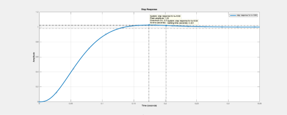
step(feedback(k(4)*g,1));grid
legend('step response for k=4000')
figure;
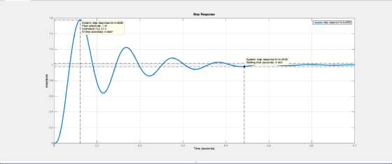
step(feedback(k(5)*g,1));grid
legend('step response for k=5000')


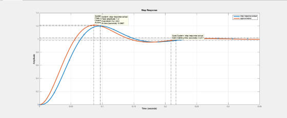
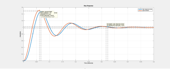
the settling times and the over shoots are not exactly the same but the second order approximation is valid.
iii) matlab plot for original system and reduced system:
clc;
clear all;
s=tf('s');
k=[1000 2000 3000 4000 5000];% gains
g=100/(s*(s+60)*(s+100));% open loop transfer function
g1=865/((s+22.21+19.28*i)*(s+22.21-19.28*i));
g2=1603/((s+17.62+35.95*i)*(s+17.62-35.95*i));
g3=2277/((s+14.13+45.58*i)*(s+14.13-45.58*i));
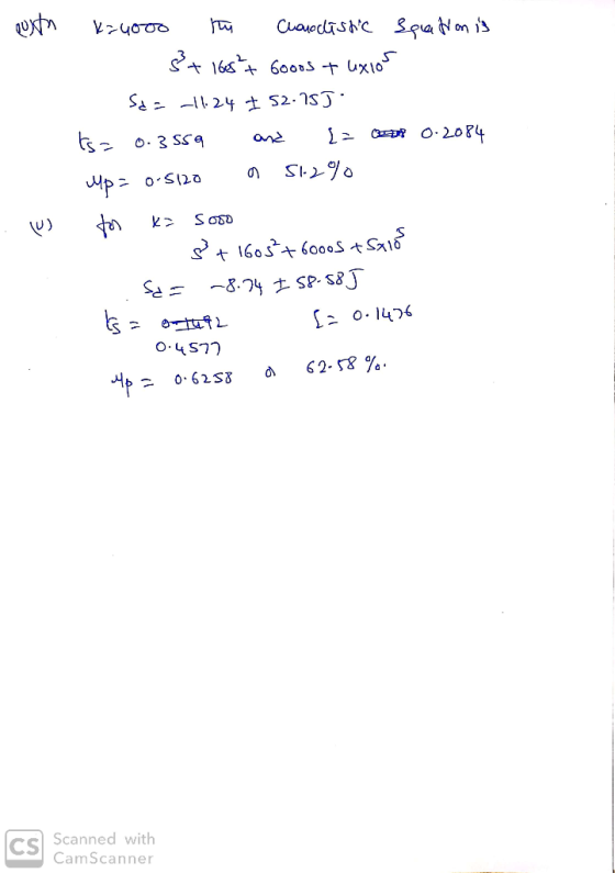
g4=2909/((s+11.24+52.75*i)*(s+11.24-52.75*i));
g5=3508/((s+8.74+58.58*i)*(s+8.74-58.58*i));
step(feedback(k(1)*g,1),g1);grid
legend('step response actual','approximated')
figure;
step(feedback(k(2)*g,1),g2);grid
legend('step response actual','approximated')
figure;
step(feedback(k(3)*g,1),g3);grid
legend('step response actual','approximated')
figure;
step(feedback(k(4)*g,1),g4);grid
legend('step response actual','approximated')
figure;
step(feedback(k(5)*g,1),g5);grid
legend('step response actual','approximated')


Add Answer to:
4. (20 points) Adapted from [DB AP5.7]: Consider the unity feedback system with variable gain K...
Please solve with detailed steps (NO MATLAB Solution).Thanks in advance 13. Consider the unity feedback system...
 Please solve with detailed steps (NO MATLAB
Solution).Thanks in advance
13. Consider the unity feedback system of Figure P9.1 with K G(s) s(s +20)(s +40) The system is operating at 20% overshoot. Design a compensator to decrease the settling time by a factor of 2 without affecting the percent overshoot and do the following: (Section: 9.3] a. Evaluate the uncompensated system's dominant poles, gain, and settling time. b. Evaluate the compensated system's dominant poles and settling time. c. Evaluate the...
Please solve with detailed steps (NO MATLAB
Solution).Thanks in advance
13. Consider the unity feedback system of Figure P9.1 with K G(s) s(s +20)(s +40) The system is operating at 20% overshoot. Design a compensator to decrease the settling time by a factor of 2 without affecting the percent overshoot and do the following: (Section: 9.3] a. Evaluate the uncompensated system's dominant poles, gain, and settling time. b. Evaluate the compensated system's dominant poles and settling time. c. Evaluate the...
2. (10 points) Adapted from [DB P8.23: The frequency response for the forward path of a unity feedback control system i...
 2. (10 points) Adapted from [DB P8.23: The frequency response for the forward path of a unity feedback control system is shown in Fig. 1. Determine the Type Number of the closed loop system and the magnitude of the steady state error in response to a unit step in the reference signal 0 60 -20 40 40 ー20 60 -80 -100 co- -120 40 -140 - 160 60 10 10 003 0 105 10-1 10° 10' 102 103 104 105...
1. Given the unity feedback system, where K(s+1(s 2) 1)(s-4) G(s) do the following: (a) Find the ...
 1. Given the unity feedback system, where K(s+1(s 2) 1)(s-4) G(s) do the following: (a) Find the root locus form. (b) Sketch the root locus. (c) Find the value of K such that the system is stable. (d) Find one value of K such that the closed-loop has a settling time less than or equal to 4 second and the percent of overshoot is less than or equal to 10 with the aid of MATLAB
1. Given the unity feedback...
1. Given the unity feedback system, where K(s+1(s 2) 1)(s-4) G(s) do the following: (a) Find the root locus form. (b) Sketch the root locus. (c) Find the value of K such that the system is stable. (d) Find one value of K such that the closed-loop has a settling time less than or equal to 4 second and the percent of overshoot is less than or equal to 10 with the aid of MATLAB
1. Given the unity feedback...
13. Consider the unity feedback system of Figure P11.1 with G(s) s(s+5s 20) The uncompensated sys...
 13. Consider the unity feedback system of Figure P11.1 with G(s) s(s+5s 20) The uncompensated system has about 55% overshoot and a peak time of 0.5 second when K 10. Do the following: [Section: 11.4] . Use frequency response methods to design a lead compensator to reduce the percent overshoot to 10%, while keeping the peak time and steady-state error about the same or less. Make any required second-order approximations. b. Use MATLAB or any other computer MATLAB ML program...
C(s) G(s) Figure 1: A block diagram for Problems 1-4 For the given unity feedback system with G(s...
 C(s) G(s) Figure 1: A block diagram for Problems 1-4 For the given unity feedback system with G(s) - s 5)3' (a) Find the location of the dominant poles to yield a 1.2 second settling time and overshoot of 15% (b) If a compensator with a zero at-1 is used to achieve the conditions of Part a, what must be the angular contribution of the compensator pole be? (c) Find the location of the compensator pole. (d) Find the gain...
3. (28 pts.) The unity feedback system with K(5+3) G(s) = (s + 1)(s + 4)(s...
 3. (28 pts.) The unity feedback system with K(5+3) G(s) = (s + 1)(s + 4)(s + 10) is operating with 12% overshoot ({=0.56). (a) the root locus plot is below, find the settling time (b) find ko (c) using frequency response techniques, design a lead compensator that will yield a twofold improvement in K, and a twofold reduction in settling time while keeping the overshoot at 12%; the Bode plot is below using the margin command and using the...
SS10. The unity-feedback system of Figure P11.1 with K (s +4) G (s) (s 2) (s 5) (s +12) is operat...
 SS10. The unity-feedback system of Figure P11.1 with K (s +4) G (s) (s 2) (s 5) (s +12) is operating with 20% overshoot. [Section: 114] a. Find the settling time. b. Find Kp c. Find the phase margin and the phase-margin frequency d. Using frequency response techniques, design a compensator that will yield a threefold improvement in Kp and a twofold reduction in settling time while keeping the overshoot at 20%.
SS10. The unity-feedback system of Figure P11.1 with...
SS10. The unity-feedback system of Figure P11.1 with K (s +4) G (s) (s 2) (s 5) (s +12) is operating with 20% overshoot. [Section: 114] a. Find the settling time. b. Find Kp c. Find the phase margin and the phase-margin frequency d. Using frequency response techniques, design a compensator that will yield a threefold improvement in Kp and a twofold reduction in settling time while keeping the overshoot at 20%.
SS10. The unity-feedback system of Figure P11.1 with...
Compensator Plant 100 R(s) sta Y(s) For the unity feedback system shown in Fig. 3.55, specify t...
 Compensator Plant 100 R(s) sta Y(s) For the unity feedback system shown in Fig. 3.55, specify the gain and pole location of the compensator so that the overall closed-loop response to a unit- step input has an overshoot of no more than 30%, and a 2% settling time of no more than 0.2 sec. Verify your design using Matlab. 3.27
Compensator Plant 100 R(s) sta Y(s)
For the unity feedback system shown in Fig. 3.55, specify the gain and pole...
Compensator Plant 100 R(s) sta Y(s) For the unity feedback system shown in Fig. 3.55, specify the gain and pole location of the compensator so that the overall closed-loop response to a unit- step input has an overshoot of no more than 30%, and a 2% settling time of no more than 0.2 sec. Verify your design using Matlab. 3.27
Compensator Plant 100 R(s) sta Y(s)
For the unity feedback system shown in Fig. 3.55, specify the gain and pole...
Problem 2. (20 pts) For the unity feedback system shown in the figure, specify the gain...
 Problem 2. (20 pts) For the unity feedback system shown in the figure, specify the gain K of the proportional controller so that the output y(t) has an overshoot of no more than 10% in response to a unit step. R9010 KG R(S) OF FOY(s) S(s + 2)
Lag Compensator Design Using Root-Locus 2. Consider the unity feedback system in Figure 1 for G(s...
 Lag Compensator Design Using Root-Locus 2. Consider the unity feedback system in Figure 1 for G(s)- s(s+3(s6) Design a lag compensation to meet the following specifications The step response settling time is to be less than 5 sec. . The step response overshoot is to be less than 17% . The steady-state error to a unit ramp input must not exceed 10%. Dynamic specifications (overshoot and settling time) can be met using proportional feedback, but a lag compensator is needed...
 Please solve with detailed steps (NO MATLAB
Solution).Thanks in advance
13. Consider the unity feedback system of Figure P9.1 with K G(s) s(s +20)(s +40) The system is operating at 20% overshoot. Design a compensator to decrease the settling time by a factor of 2 without affecting the percent overshoot and do the following: (Section: 9.3] a. Evaluate the uncompensated system's dominant poles, gain, and settling time. b. Evaluate the compensated system's dominant poles and settling time. c. Evaluate the...
Please solve with detailed steps (NO MATLAB
Solution).Thanks in advance
13. Consider the unity feedback system of Figure P9.1 with K G(s) s(s +20)(s +40) The system is operating at 20% overshoot. Design a compensator to decrease the settling time by a factor of 2 without affecting the percent overshoot and do the following: (Section: 9.3] a. Evaluate the uncompensated system's dominant poles, gain, and settling time. b. Evaluate the compensated system's dominant poles and settling time. c. Evaluate the...
 2. (10 points) Adapted from [DB P8.23: The frequency response for the forward path of a unity feedback control system is shown in Fig. 1. Determine the Type Number of the closed loop system and the magnitude of the steady state error in response to a unit step in the reference signal 0 60 -20 40 40 ー20 60 -80 -100 co- -120 40 -140 - 160 60 10 10 003 0 105 10-1 10° 10' 102 103 104 105...
 1. Given the unity feedback system, where K(s+1(s 2) 1)(s-4) G(s) do the following: (a) Find the root locus form. (b) Sketch the root locus. (c) Find the value of K such that the system is stable. (d) Find one value of K such that the closed-loop has a settling time less than or equal to 4 second and the percent of overshoot is less than or equal to 10 with the aid of MATLAB
1. Given the unity feedback...
1. Given the unity feedback system, where K(s+1(s 2) 1)(s-4) G(s) do the following: (a) Find the root locus form. (b) Sketch the root locus. (c) Find the value of K such that the system is stable. (d) Find one value of K such that the closed-loop has a settling time less than or equal to 4 second and the percent of overshoot is less than or equal to 10 with the aid of MATLAB
1. Given the unity feedback...
 13. Consider the unity feedback system of Figure P11.1 with G(s) s(s+5s 20) The uncompensated system has about 55% overshoot and a peak time of 0.5 second when K 10. Do the following: [Section: 11.4] . Use frequency response methods to design a lead compensator to reduce the percent overshoot to 10%, while keeping the peak time and steady-state error about the same or less. Make any required second-order approximations. b. Use MATLAB or any other computer MATLAB ML program...
 C(s) G(s) Figure 1: A block diagram for Problems 1-4 For the given unity feedback system with G(s) - s 5)3' (a) Find the location of the dominant poles to yield a 1.2 second settling time and overshoot of 15% (b) If a compensator with a zero at-1 is used to achieve the conditions of Part a, what must be the angular contribution of the compensator pole be? (c) Find the location of the compensator pole. (d) Find the gain...
 3. (28 pts.) The unity feedback system with K(5+3) G(s) = (s + 1)(s + 4)(s + 10) is operating with 12% overshoot ({=0.56). (a) the root locus plot is below, find the settling time (b) find ko (c) using frequency response techniques, design a lead compensator that will yield a twofold improvement in K, and a twofold reduction in settling time while keeping the overshoot at 12%; the Bode plot is below using the margin command and using the...
 SS10. The unity-feedback system of Figure P11.1 with K (s +4) G (s) (s 2) (s 5) (s +12) is operating with 20% overshoot. [Section: 114] a. Find the settling time. b. Find Kp c. Find the phase margin and the phase-margin frequency d. Using frequency response techniques, design a compensator that will yield a threefold improvement in Kp and a twofold reduction in settling time while keeping the overshoot at 20%.
SS10. The unity-feedback system of Figure P11.1 with...
SS10. The unity-feedback system of Figure P11.1 with K (s +4) G (s) (s 2) (s 5) (s +12) is operating with 20% overshoot. [Section: 114] a. Find the settling time. b. Find Kp c. Find the phase margin and the phase-margin frequency d. Using frequency response techniques, design a compensator that will yield a threefold improvement in Kp and a twofold reduction in settling time while keeping the overshoot at 20%.
SS10. The unity-feedback system of Figure P11.1 with...
 Compensator Plant 100 R(s) sta Y(s) For the unity feedback system shown in Fig. 3.55, specify the gain and pole location of the compensator so that the overall closed-loop response to a unit- step input has an overshoot of no more than 30%, and a 2% settling time of no more than 0.2 sec. Verify your design using Matlab. 3.27
Compensator Plant 100 R(s) sta Y(s)
For the unity feedback system shown in Fig. 3.55, specify the gain and pole...
Compensator Plant 100 R(s) sta Y(s) For the unity feedback system shown in Fig. 3.55, specify the gain and pole location of the compensator so that the overall closed-loop response to a unit- step input has an overshoot of no more than 30%, and a 2% settling time of no more than 0.2 sec. Verify your design using Matlab. 3.27
Compensator Plant 100 R(s) sta Y(s)
For the unity feedback system shown in Fig. 3.55, specify the gain and pole...
 Problem 2. (20 pts) For the unity feedback system shown in the figure, specify the gain K of the proportional controller so that the output y(t) has an overshoot of no more than 10% in response to a unit step. R9010 KG R(S) OF FOY(s) S(s + 2)
 Lag Compensator Design Using Root-Locus 2. Consider the unity feedback system in Figure 1 for G(s)- s(s+3(s6) Design a lag compensation to meet the following specifications The step response settling time is to be less than 5 sec. . The step response overshoot is to be less than 17% . The steady-state error to a unit ramp input must not exceed 10%. Dynamic specifications (overshoot and settling time) can be met using proportional feedback, but a lag compensator is needed...
Most questions answered within 3 hours.
-
1- What is the freezing point of pure water (in degrees
Celsius)?
2-
he molar mass...
asked 32 minutes ago -
Determine the direction of the force that will act on the charge
in each of the...
asked 38 minutes ago -
You purchase your daily coffee at the Chemist’s Coffeehouse and
have a choice of two cups:...
asked 3 hours ago -
Which of the following pairs of chemicals could be used to make
a buffer solution?
A.)...
asked 3 hours ago -
Problem 16-51 Sales
Activity Variance (LO 16-3)Odessa, Inc., reports the following
information concerning operations for the...
asked 3 hours ago -
Pictured on the right are thee point charges Q1 = 18.4 μC, Q2 =
-30.6 μC,...
asked 3 hours ago -
A graduate student is conducting research in psychology and
needs to obtain the IQ scores of...
asked 4 hours ago -
R2.84: There are 2 defective products in a production lot of 10.
An inspector randomly selected...
asked 5 hours ago -
Consider the following equilibrium system: COCl2(g) CO(g) +
Cl2(g) A 10.00 L evacuated flask is filled...
asked 6 hours ago -
1) What are the two distinct steps that one needs to perform
when developing a data...
asked 6 hours ago -
2) Write a C++ program that uses a class called “Degree” to
obtain the trigonometric
values...
asked 7 hours ago -
1. In eukaryotic cells the genomes of
&
asked 7 hours ago