
Homework Answers

Add Answer to:
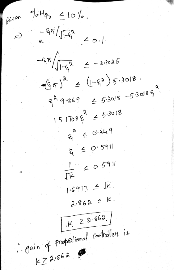
Problem 2. (20 pts) For the unity feedback system shown in the figure, specify the gain...
Q2. For the unity feedback system shown specify the gain K of the proportional controller so...
 Q2. For the unity feedback system shown specify the gain K of the proportional controller so that the outputy() has an overshoot of no more than 10% in response to a unit step. s) o o Y(s) s(s+2)
Compensator Plant 100 R(s) sta Y(s) For the unity feedback system shown in Fig. 3.55, specify t...
 Compensator Plant 100 R(s) sta Y(s) For the unity feedback system shown in Fig. 3.55, specify the gain and pole location of the compensator so that the overall closed-loop response to a unit- step input has an overshoot of no more than 30%, and a 2% settling time of no more than 0.2 sec. Verify your design using Matlab. 3.27
Compensator Plant 100 R(s) sta Y(s)
For the unity feedback system shown in Fig. 3.55, specify the gain and pole...
Compensator Plant 100 R(s) sta Y(s) For the unity feedback system shown in Fig. 3.55, specify the gain and pole location of the compensator so that the overall closed-loop response to a unit- step input has an overshoot of no more than 30%, and a 2% settling time of no more than 0.2 sec. Verify your design using Matlab. 3.27
Compensator Plant 100 R(s) sta Y(s)
For the unity feedback system shown in Fig. 3.55, specify the gain and pole...
Lag Compensator Design Using Root-Locus 2. Consider the unity feedback system in Figure 1 for G(s...
 Lag Compensator Design Using Root-Locus 2. Consider the unity feedback system in Figure 1 for G(s)- s(s+3(s6) Design a lag compensation to meet the following specifications The step response settling time is to be less than 5 sec. . The step response overshoot is to be less than 17% . The steady-state error to a unit ramp input must not exceed 10%. Dynamic specifications (overshoot and settling time) can be met using proportional feedback, but a lag compensator is needed...
Problem 4) (20 Pts.) A Proportional controller is simply a gain block. In figure below, it...
 Problem 4) (20 Pts.) A Proportional controller is simply a gain block. In figure below, it is the block with gain 2nd order underdamped plant as shown. Kc which is behind the a) Simplify below block diagram to obtain the overall feedback system transfer funion)R(G) b) Choose Kc so that the overall feedback system transfer function G(s) has 50% overshoot due to a step input (called quarter decay ratio tuning) d) The feedback system transfer function Gs)- is faster than...
PROBLEM 4 Suppose that a system is shown in Figure 4. There are three controllers that might be incorporated into this system. 1. Ge (s)-K (proportional (P) controller) 2. GS)K/s (integral (I) contro...
 PROBLEM 4 Suppose that a system is shown in Figure 4. There are three controllers that might be incorporated into this system. 1. Ge (s)-K (proportional (P) controller) 2. GS)K/s (integral (I) controller) 3. G (s)K(1+1/s) (proportional, integral (PI) controller) The system requirements are T, < 10 seconds and P0 10% for a unit step response. (a) For the (P) controller, write a piece of MATLAB code to plot root locus for 0<K<,and find the K value so that the...
Automatic Control In unity feedback system with Gs) (s-IXs-2) With out controller, is this system stable, and why? For Gc K (proportional control) sketch the root locus. Find the range of K to mak...
 Automatic Control
In unity feedback system with Gs) (s-IXs-2) With out controller, is this system stable, and why? For Gc K (proportional control) sketch the root locus. Find the range of K to make the system stable. Determine the range of K, so that the system has no overshoot Determine the range of K for steady state error to unit step input less than 20% a) b) c) d) e)
In unity feedback system with Gs) (s-IXs-2) With out controller,...
Automatic Control
In unity feedback system with Gs) (s-IXs-2) With out controller, is this system stable, and why? For Gc K (proportional control) sketch the root locus. Find the range of K to make the system stable. Determine the range of K, so that the system has no overshoot Determine the range of K for steady state error to unit step input less than 20% a) b) c) d) e)
In unity feedback system with Gs) (s-IXs-2) With out controller,...
Question 5 or a unity feedback system in Figure 4 C(s) (s+40%s +100) Figure 4 a) Find the value o...
 Question 5 or a unity feedback system in Figure 4 C(s) (s+40%s +100) Figure 4 a) Find the value of gain, K, to yield a closed-loop response with 20% overshoot when the system is under a step input. Check the system stability at this gain value (use either Nyquist criterion or Margins). Assume the system is under a unity step input. Use Simulink to obtain and compare the time responses with and without gain adjustment and discuss how the response...
4. (20 points) Adapted from [DB AP5.7]: Consider the unity feedback system with variable gain K...
 4. (20 points) Adapted from [DB AP5.7]: Consider the unity feedback system with variable gain K shown (a) Assume that the complex poles dominate and estimate the 2% settling time and percent overshoot (b) Using MATLAB, determine the actual settling times and percent overshoots of the full third- in Figure 2. We are constrained to keep 1000 s K 5000. in response to a unit step for K 1000, 2000, 3000, 4000, and 5000 order system for the values of...
1. Consider the unity feedback system shown in figure 1 with G(S) -2sti a) Determine the...
 1. Consider the unity feedback system shown in figure 1 with G(S) -2sti a) Determine the closed loop transfer function TF(s) γ(s) R(s) What are the poles and zeros of TF1(s)? [2 marks] b) For TF(s), calculate the DC gain, natural frequency and damping ratio. Classify TF1(s) as underdamped overdamped, critically damped or undamped [3 marks] c) Use the initial value theorem and final value theorem to determine the initial value (Mo) and final value (M) of the [2 marks]...
4) A unity feedback control system shown in Figure 2 has the following controller and process with the transfer functions: m(60100c Prs(s +10(s+7.5) a) Obtain the open- and closed-loop transfer f...
 4) A unity feedback control system shown in Figure 2 has the following controller and process with the transfer functions: m(60100c Prs(s +10(s+7.5) a) Obtain the open- and closed-loop transfer functions of the system. b) Obtain the stability conditions using the Routh-Hurwitz criterion. e) Setting by trial-and-error some values for Kp, Ki, and Ko, obtain the time response for minimum overshoot and minimum settling time by Matlab/Simulink. Y(s) R(s) E(s) Fig. 2: Unity feedback control system
4) A unity feedback...
4) A unity feedback control system shown in Figure 2 has the following controller and process with the transfer functions: m(60100c Prs(s +10(s+7.5) a) Obtain the open- and closed-loop transfer functions of the system. b) Obtain the stability conditions using the Routh-Hurwitz criterion. e) Setting by trial-and-error some values for Kp, Ki, and Ko, obtain the time response for minimum overshoot and minimum settling time by Matlab/Simulink. Y(s) R(s) E(s) Fig. 2: Unity feedback control system
4) A unity feedback...
 Q2. For the unity feedback system shown specify the gain K of the proportional controller so that the outputy() has an overshoot of no more than 10% in response to a unit step. s) o o Y(s) s(s+2)
 Compensator Plant 100 R(s) sta Y(s) For the unity feedback system shown in Fig. 3.55, specify the gain and pole location of the compensator so that the overall closed-loop response to a unit- step input has an overshoot of no more than 30%, and a 2% settling time of no more than 0.2 sec. Verify your design using Matlab. 3.27
Compensator Plant 100 R(s) sta Y(s)
For the unity feedback system shown in Fig. 3.55, specify the gain and pole...
Compensator Plant 100 R(s) sta Y(s) For the unity feedback system shown in Fig. 3.55, specify the gain and pole location of the compensator so that the overall closed-loop response to a unit- step input has an overshoot of no more than 30%, and a 2% settling time of no more than 0.2 sec. Verify your design using Matlab. 3.27
Compensator Plant 100 R(s) sta Y(s)
For the unity feedback system shown in Fig. 3.55, specify the gain and pole...
 Lag Compensator Design Using Root-Locus 2. Consider the unity feedback system in Figure 1 for G(s)- s(s+3(s6) Design a lag compensation to meet the following specifications The step response settling time is to be less than 5 sec. . The step response overshoot is to be less than 17% . The steady-state error to a unit ramp input must not exceed 10%. Dynamic specifications (overshoot and settling time) can be met using proportional feedback, but a lag compensator is needed...
 Problem 4) (20 Pts.) A Proportional controller is simply a gain block. In figure below, it is the block with gain 2nd order underdamped plant as shown. Kc which is behind the a) Simplify below block diagram to obtain the overall feedback system transfer funion)R(G) b) Choose Kc so that the overall feedback system transfer function G(s) has 50% overshoot due to a step input (called quarter decay ratio tuning) d) The feedback system transfer function Gs)- is faster than...
 PROBLEM 4 Suppose that a system is shown in Figure 4. There are three controllers that might be incorporated into this system. 1. Ge (s)-K (proportional (P) controller) 2. GS)K/s (integral (I) controller) 3. G (s)K(1+1/s) (proportional, integral (PI) controller) The system requirements are T, < 10 seconds and P0 10% for a unit step response. (a) For the (P) controller, write a piece of MATLAB code to plot root locus for 0<K<,and find the K value so that the...
 Automatic Control
In unity feedback system with Gs) (s-IXs-2) With out controller, is this system stable, and why? For Gc K (proportional control) sketch the root locus. Find the range of K to make the system stable. Determine the range of K, so that the system has no overshoot Determine the range of K for steady state error to unit step input less than 20% a) b) c) d) e)
In unity feedback system with Gs) (s-IXs-2) With out controller,...
Automatic Control
In unity feedback system with Gs) (s-IXs-2) With out controller, is this system stable, and why? For Gc K (proportional control) sketch the root locus. Find the range of K to make the system stable. Determine the range of K, so that the system has no overshoot Determine the range of K for steady state error to unit step input less than 20% a) b) c) d) e)
In unity feedback system with Gs) (s-IXs-2) With out controller,...
 Question 5 or a unity feedback system in Figure 4 C(s) (s+40%s +100) Figure 4 a) Find the value of gain, K, to yield a closed-loop response with 20% overshoot when the system is under a step input. Check the system stability at this gain value (use either Nyquist criterion or Margins). Assume the system is under a unity step input. Use Simulink to obtain and compare the time responses with and without gain adjustment and discuss how the response...
 4. (20 points) Adapted from [DB AP5.7]: Consider the unity feedback system with variable gain K shown (a) Assume that the complex poles dominate and estimate the 2% settling time and percent overshoot (b) Using MATLAB, determine the actual settling times and percent overshoots of the full third- in Figure 2. We are constrained to keep 1000 s K 5000. in response to a unit step for K 1000, 2000, 3000, 4000, and 5000 order system for the values of...
 1. Consider the unity feedback system shown in figure 1 with G(S) -2sti a) Determine the closed loop transfer function TF(s) γ(s) R(s) What are the poles and zeros of TF1(s)? [2 marks] b) For TF(s), calculate the DC gain, natural frequency and damping ratio. Classify TF1(s) as underdamped overdamped, critically damped or undamped [3 marks] c) Use the initial value theorem and final value theorem to determine the initial value (Mo) and final value (M) of the [2 marks]...
 4) A unity feedback control system shown in Figure 2 has the following controller and process with the transfer functions: m(60100c Prs(s +10(s+7.5) a) Obtain the open- and closed-loop transfer functions of the system. b) Obtain the stability conditions using the Routh-Hurwitz criterion. e) Setting by trial-and-error some values for Kp, Ki, and Ko, obtain the time response for minimum overshoot and minimum settling time by Matlab/Simulink. Y(s) R(s) E(s) Fig. 2: Unity feedback control system
4) A unity feedback...
4) A unity feedback control system shown in Figure 2 has the following controller and process with the transfer functions: m(60100c Prs(s +10(s+7.5) a) Obtain the open- and closed-loop transfer functions of the system. b) Obtain the stability conditions using the Routh-Hurwitz criterion. e) Setting by trial-and-error some values for Kp, Ki, and Ko, obtain the time response for minimum overshoot and minimum settling time by Matlab/Simulink. Y(s) R(s) E(s) Fig. 2: Unity feedback control system
4) A unity feedback...
Most questions answered within 3 hours.
-
Considering gravitational time dilation, calculate the time that
passes in Earth’s surface while 1 hour passes...
asked 22 minutes ago -
Minitab Problem: Take the Lake Hume June rainfall data and find
use the processes outlined in...
asked 1 hour ago -
X Company is trying to decide whether to continue using old
equipment to make Product A...
asked 1 hour ago -
IN PYTHON ONLY !! Program 2: Re-work
program #5 (WeeklyHours) from the previous assignment such that...
asked 1 hour ago -
The average length of time between arrivals at a turnpike
toll-booth is 26 seconds. What is...
asked 3 hours ago -
(a) A piston at 6.1 atm contains a gas that occupies a volume of
3.5 L....
asked 4 hours ago -
Please answer true or false. Words
cannot be changed or added in to make it true...
asked 4 hours ago -
An empty test tube weighs 15.923 grams. Then,
MgCl2•6H2O is added into the test tube. After...
asked 4 hours ago -
Assume memory access is 10 units of time and disk access is
10000 units of time....
asked 5 hours ago -
1. Are all good samples random?
2. Magazines often report surveys giving statistics such as “63%...
asked 5 hours ago -
Under all the various types of market structures, firms
must eventually earn some economic profits for...
asked 5 hours ago -
Consider the following fitness regime for a single locus trait
with two co-dominant alleles: w11 =...
asked 5 hours ago