![QUESTION 1 Consider the crout diagram n Figure 1, R=10?·Le 100 mH and the thynstor s trggered after a delay of radans. V,-220 v 50 Hz. 1.1 Determine how many radians the current will flow in each cycle of the supply Hint ?, sin(ax + ?-9)-(1-sin(a-?),T 12 Sketch labelled waveforms of Ve. i, and V. 13 Calculate the average load voltage 14 Calculate the average load current [18] V. V. Figure 1](http://img.homeworklib.com/questions/15939540-b033-11eb-b654-edff0654e34e.png?x-oss-process=image/resize,w_560)
Homework Answers


Add Answer to:
QUESTION 1 Consider the crout diagram n Figure 1, R=10?·Le 100 mH and the thynstor s...
(i) (ii) Draw the structural diagram of a Gate Turn-Off (GTO) thyristor. [7%] Explain the operation...
 (i) (ii) Draw the structural diagram of a Gate Turn-Off (GTO) thyristor. [7%] Explain the operation of GTO and clearly state the voltage and frequency range for its application [15%] State four advantages of GTOs when compared to conventional thyristors. (iii) [8%] (b) Consider the single-phase full bridge rectifier shown below where R=6 12, L = 6 mH, E = 60 V and the ac source voltage is 230 V, 50 Hz. * * 13 பண்பு 14* (i) For continuous...
Question 1 220 Vrms 50 Hz 10:1 CR Figure 1 Figure 1 shows the circuit diagram...
 Question 1 220 Vrms 50 Hz 10:1 CR Figure 1 Figure 1 shows the circuit diagram for a simple d.c. power supply. a. Identify the type of rectifier circuit represented in figure I and explain the operation of the circuit with reference to the function of each component within the circuit. b. Sketch to scale the voltage across R as a function of time showing its relationship to the secondary voltage from the transformer. Question 2 A 5.0V stabilized power...
A three phase full-wave AC controller in Figure Q5(a) is supplied to a system with Y...
 A three phase full-wave AC controller in Figure Q5(a) is supplied to a system with Y connected load system. The load consists of R = 100 and L = 0.01 mH which are connected in series between them. The line-to-line input voltage is given as 208 V with 50 Hz and the delay angle is given as a = 271/3. (1) Calculate the rms value of output phase voltage. (3 marks) (ii) Determine the power factor at output based on...
Draw a well-labelled circuit diagram of a Buck-Boost converter and draw the equivalent circuit diagrams for...
 Draw a well-labelled circuit diagram of a Buck-Boost converter and draw the equivalent circuit diagrams for its two modes of operation (no waveforms). Label all circuits. [30%] With the help of the circuits in 2(a)(i), explain the working of a Buck-Boost converter. [20%] (ii) (b) Consider the following single-phase, half-wave rectifier circuit that is used to charge a battery through a resistor R. GO v, = Vm sin ot = (i) Prove that the average value of the charging current...
b. Consider the single-phase fully controlled of thyristor bridge rectifier supplies a load consists of R-L...
 b. Consider the single-phase fully controlled of thyristor bridge rectifier supplies a load consists of R-L load and Vee in series as shown in Figure Q2 (b). The parameters for this circuit are as follows: supply voltage is 120 Vrms at 60 Hz, DC voltage, Voe equal to 10 v. i. Sketch the waveforms for output voltage, thyristor current, diode current and output current (CO2: PO2 - 5 marks) Calculate the output voltage, Va at a = Tt/2. (CO2: PO2...
1. A 50 Hz 3-phase Have wave uncontrolled rectifier circuit is used to supply a resistive load of...
 1. A 50 Hz 3-phase Have wave uncontrolled rectifier circuit is used to supply a resistive load of 100 ohms. The supply is unbalanced and defined as v.-127.28 cos (ot) V 127.28 sin (ot-0.5236) V n63.64 cos (ot+2.0944) V a) Draw the circuit diagram. b) Draw the three phase voltages wave forms. c) Use phasor diagram or any other method to obtain the line voltages v and d) Draw the line voltages v and v wave forms. e) Derive an...
can you calculate and explain why? thanks A single-phase thyristor rectifier as 50 Hz source. The...
 can you calculate and explain why? thanks
A single-phase thyristor rectifier as 50 Hz source. The rectifier delivers a DC voltage of 150 V to a highly inductive depicted in Figure 1 is fed from a 220 V rms, 1. load with a resistive value of 10 Q. SCR, T SCR2 + is Vo SCR3 SCR T Figure 1 (a) for a delay angle component indicating its phase shift with respect to the input voltage v, Sketch the net rectifier...
can you calculate and explain why? thanks
A single-phase thyristor rectifier as 50 Hz source. The rectifier delivers a DC voltage of 150 V to a highly inductive depicted in Figure 1 is fed from a 220 V rms, 1. load with a resistive value of 10 Q. SCR, T SCR2 + is Vo SCR3 SCR T Figure 1 (a) for a delay angle component indicating its phase shift with respect to the input voltage v, Sketch the net rectifier...
1) Would it be possible if anyone could use the same exact values as stated from the question? 2)...
 1) Would it be possible if anyone could use the same exact
values as stated from the question?
2) In addition, we would like to understand why Vmp = 120xroot2
/ root3 ?
3) Also, how do we derive the voltage drop due to
commutation?
4) Will there be a commutation period in your output waveform?
If yes, where is it?
6-2 In the circuit of Fig. P6-2, the balanced three-phase voltages va, v, and v have an rms value...
1) Would it be possible if anyone could use the same exact
values as stated from the question?
2) In addition, we would like to understand why Vmp = 120xroot2
/ root3 ?
3) Also, how do we derive the voltage drop due to
commutation?
4) Will there be a commutation period in your output waveform?
If yes, where is it?
6-2 In the circuit of Fig. P6-2, the balanced three-phase voltages va, v, and v have an rms value...
In the figure, R = 13.0 ?, C = 7.60 ?F, and L = 40.0 mH....
 In the figure, R = 13.0 ?, C = 7.60 ?F, and L = 40.0 mH. The
generator provides a sinusoidal voltage of 75 V (rms) and frequency
f = 690 Hz . Calculate the rms current.
Find the rms voltage, Vab.
Find the rms voltage, Vbc.
Find the rms voltage, Vcd.
Find the rms voltage, Vbd.
Find the rms voltage, Vad.
At what average rate is energy dissipated by the capacitor?
At what average rate is energy dissipated by...
In the figure, R = 13.0 ?, C = 7.60 ?F, and L = 40.0 mH. The
generator provides a sinusoidal voltage of 75 V (rms) and frequency
f = 690 Hz . Calculate the rms current.
Find the rms voltage, Vab.
Find the rms voltage, Vbc.
Find the rms voltage, Vcd.
Find the rms voltage, Vbd.
Find the rms voltage, Vad.
At what average rate is energy dissipated by the capacitor?
At what average rate is energy dissipated by...
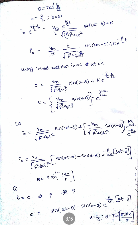
The single-phase full converter as shown in Figure 8-1 has an RL load having L =...
 The single-phase full converter as shown in Figure 8-1 has an RL load having L = 5 mH, R-0.8 Ω, and E -0 V. The input voltage is Vs = 120 V at(rms) 60 Hz. The delay angle or-α-300 Calculate the performance parameters. Assume ideal thyristor switches. the rms thyristor current IR Figure 8-1 Single-Phase Full Converter T1 T4 太T2 0
 (i) (ii) Draw the structural diagram of a Gate Turn-Off (GTO) thyristor. [7%] Explain the operation of GTO and clearly state the voltage and frequency range for its application [15%] State four advantages of GTOs when compared to conventional thyristors. (iii) [8%] (b) Consider the single-phase full bridge rectifier shown below where R=6 12, L = 6 mH, E = 60 V and the ac source voltage is 230 V, 50 Hz. * * 13 பண்பு 14* (i) For continuous...
 Question 1 220 Vrms 50 Hz 10:1 CR Figure 1 Figure 1 shows the circuit diagram for a simple d.c. power supply. a. Identify the type of rectifier circuit represented in figure I and explain the operation of the circuit with reference to the function of each component within the circuit. b. Sketch to scale the voltage across R as a function of time showing its relationship to the secondary voltage from the transformer. Question 2 A 5.0V stabilized power...
 A three phase full-wave AC controller in Figure Q5(a) is supplied to a system with Y connected load system. The load consists of R = 100 and L = 0.01 mH which are connected in series between them. The line-to-line input voltage is given as 208 V with 50 Hz and the delay angle is given as a = 271/3. (1) Calculate the rms value of output phase voltage. (3 marks) (ii) Determine the power factor at output based on...
 Draw a well-labelled circuit diagram of a Buck-Boost converter and draw the equivalent circuit diagrams for its two modes of operation (no waveforms). Label all circuits. [30%] With the help of the circuits in 2(a)(i), explain the working of a Buck-Boost converter. [20%] (ii) (b) Consider the following single-phase, half-wave rectifier circuit that is used to charge a battery through a resistor R. GO v, = Vm sin ot = (i) Prove that the average value of the charging current...
 b. Consider the single-phase fully controlled of thyristor bridge rectifier supplies a load consists of R-L load and Vee in series as shown in Figure Q2 (b). The parameters for this circuit are as follows: supply voltage is 120 Vrms at 60 Hz, DC voltage, Voe equal to 10 v. i. Sketch the waveforms for output voltage, thyristor current, diode current and output current (CO2: PO2 - 5 marks) Calculate the output voltage, Va at a = Tt/2. (CO2: PO2...
 1. A 50 Hz 3-phase Have wave uncontrolled rectifier circuit is used to supply a resistive load of 100 ohms. The supply is unbalanced and defined as v.-127.28 cos (ot) V 127.28 sin (ot-0.5236) V n63.64 cos (ot+2.0944) V a) Draw the circuit diagram. b) Draw the three phase voltages wave forms. c) Use phasor diagram or any other method to obtain the line voltages v and d) Draw the line voltages v and v wave forms. e) Derive an...
 can you calculate and explain why? thanks
A single-phase thyristor rectifier as 50 Hz source. The rectifier delivers a DC voltage of 150 V to a highly inductive depicted in Figure 1 is fed from a 220 V rms, 1. load with a resistive value of 10 Q. SCR, T SCR2 + is Vo SCR3 SCR T Figure 1 (a) for a delay angle component indicating its phase shift with respect to the input voltage v, Sketch the net rectifier...
can you calculate and explain why? thanks
A single-phase thyristor rectifier as 50 Hz source. The rectifier delivers a DC voltage of 150 V to a highly inductive depicted in Figure 1 is fed from a 220 V rms, 1. load with a resistive value of 10 Q. SCR, T SCR2 + is Vo SCR3 SCR T Figure 1 (a) for a delay angle component indicating its phase shift with respect to the input voltage v, Sketch the net rectifier...
 1) Would it be possible if anyone could use the same exact
values as stated from the question?
2) In addition, we would like to understand why Vmp = 120xroot2
/ root3 ?
3) Also, how do we derive the voltage drop due to
commutation?
4) Will there be a commutation period in your output waveform?
If yes, where is it?
6-2 In the circuit of Fig. P6-2, the balanced three-phase voltages va, v, and v have an rms value...
1) Would it be possible if anyone could use the same exact
values as stated from the question?
2) In addition, we would like to understand why Vmp = 120xroot2
/ root3 ?
3) Also, how do we derive the voltage drop due to
commutation?
4) Will there be a commutation period in your output waveform?
If yes, where is it?
6-2 In the circuit of Fig. P6-2, the balanced three-phase voltages va, v, and v have an rms value...
 In the figure, R = 13.0 ?, C = 7.60 ?F, and L = 40.0 mH. The
generator provides a sinusoidal voltage of 75 V (rms) and frequency
f = 690 Hz . Calculate the rms current.
Find the rms voltage, Vab.
Find the rms voltage, Vbc.
Find the rms voltage, Vcd.
Find the rms voltage, Vbd.
Find the rms voltage, Vad.
At what average rate is energy dissipated by the capacitor?
At what average rate is energy dissipated by...
In the figure, R = 13.0 ?, C = 7.60 ?F, and L = 40.0 mH. The
generator provides a sinusoidal voltage of 75 V (rms) and frequency
f = 690 Hz . Calculate the rms current.
Find the rms voltage, Vab.
Find the rms voltage, Vbc.
Find the rms voltage, Vcd.
Find the rms voltage, Vbd.
Find the rms voltage, Vad.
At what average rate is energy dissipated by the capacitor?
At what average rate is energy dissipated by...
 The single-phase full converter as shown in Figure 8-1 has an RL load having L = 5 mH, R-0.8 Ω, and E -0 V. The input voltage is Vs = 120 V at(rms) 60 Hz. The delay angle or-α-300 Calculate the performance parameters. Assume ideal thyristor switches. the rms thyristor current IR Figure 8-1 Single-Phase Full Converter T1 T4 太T2 0
Most questions answered within 3 hours.
-
1. In the short run, the marginal product of labor increases
then decreases because of what?...
asked 19 minutes ago -
A farmer wants to compare the tastiness and juiciness of
tomatoes grown with three amounts of...
asked 1 hour ago -
What is facilitated diffusion and how does it differ from
symport and antiport transportation? How do...
asked 1 hour ago -
if a firm producing 100 units at $5.00 each experience
an 80% experience curve, what will...
asked 2 hours ago -
A solid, uniform disk of radius 0.250 m and mass 53.7 kg rolls
down a ramp...
asked 4 hours ago -
Given the following table of high speed internet access vs.
annual home income:
Home Income
%...
asked 5 hours ago -
A baseball batter hits a 0.145kg baseball straight up into the
air. The baseball leaves the...
asked 5 hours ago -
An FM modulator is tested using
single-tone baseband signal with frequency of 50kHz and a sprectrum...
asked 6 hours ago -
Write the ionic equations for the first stage of salts
hydrolysis.
Anion, Cation?
Na2S
NiSO4
K2SO4...
asked 7 hours ago -
suppose there is a normally distributed population with a mean of
250 and a standard deviation...
asked 8 hours ago -
Question Three
Suppose you as project manager are using the Waterfall
development methodology on a large...
asked 9 hours ago -
Which statement is not true about welfare in Canada?
A.Benefits typically vary based on one's ability...
asked 9 hours ago