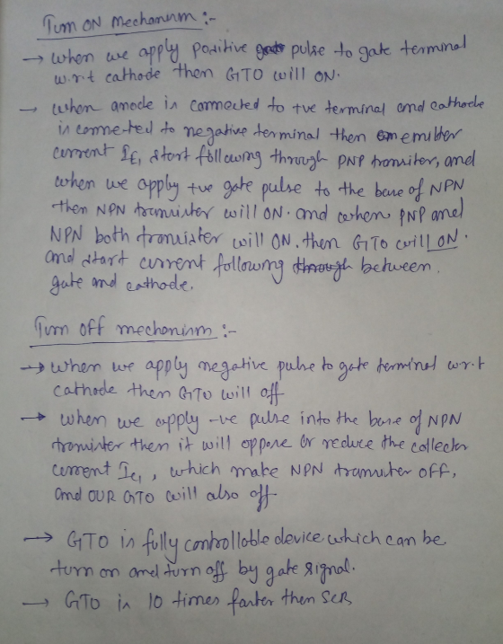
![(i) (ii) Draw the structural diagram of a Gate Turn-Off (GTO) thyristor. [7%] Explain the operation of GTO and clearly state](http://img.homeworklib.com/questions/74dbd2f0-c806-11eb-865d-47e5ac0cc9d7.png?x-oss-process=image/resize,w_560)
Homework Answers
I TRIED MY LEVEL BEST TO EXPLAIN EACH POINT IN DETAIL.
I HOPE ITS HELPFULL FOR YOU.
STILL YOU HAVE ANY DOUBT PLEASE COMMENT. DOUBTS ARE ALWAYS WELCOME.
THANK YOU
a.)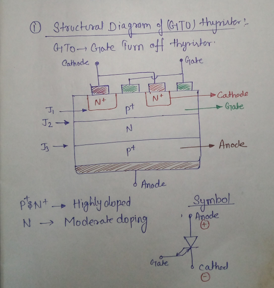


b)
i.)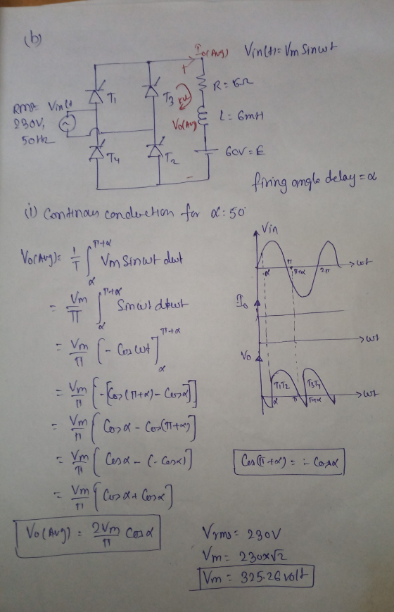

Add Answer to:
(i) (ii) Draw the structural diagram of a Gate Turn-Off (GTO) thyristor. [7%] Explain the operation...
i want the answer with detales Single-Phase Controlled Rectifier Exercise Derive the expressions of the average...
 i want the answer with detales
Single-Phase Controlled Rectifier Exercise Derive the expressions of the average load voltage and current in single-phase half-wave controlled rectifiers and resistive load. Draw the waveforms of supply voltage. output voltage, output current, thyristor voltage and thyristor current Exercise In a single-phase half-wave controlled rectifier and resistive kad, it is desired to get an average load voltage of 80 V. Determine the firing angle if the ac supply voltage is 230 V. If the load...
i want the answer with detales
Single-Phase Controlled Rectifier Exercise Derive the expressions of the average load voltage and current in single-phase half-wave controlled rectifiers and resistive load. Draw the waveforms of supply voltage. output voltage, output current, thyristor voltage and thyristor current Exercise In a single-phase half-wave controlled rectifier and resistive kad, it is desired to get an average load voltage of 80 V. Determine the firing angle if the ac supply voltage is 230 V. If the load...
can you calculate and explain why? thanks A single-phase thyristor rectifier as 50 Hz source. The...
 can you calculate and explain why? thanks
A single-phase thyristor rectifier as 50 Hz source. The rectifier delivers a DC voltage of 150 V to a highly inductive depicted in Figure 1 is fed from a 220 V rms, 1. load with a resistive value of 10 Q. SCR, T SCR2 + is Vo SCR3 SCR T Figure 1 (a) for a delay angle component indicating its phase shift with respect to the input voltage v, Sketch the net rectifier...
can you calculate and explain why? thanks
A single-phase thyristor rectifier as 50 Hz source. The rectifier delivers a DC voltage of 150 V to a highly inductive depicted in Figure 1 is fed from a 220 V rms, 1. load with a resistive value of 10 Q. SCR, T SCR2 + is Vo SCR3 SCR T Figure 1 (a) for a delay angle component indicating its phase shift with respect to the input voltage v, Sketch the net rectifier...
Draw a well-labelled circuit diagram of a Buck-Boost converter and draw the equivalent circuit diagrams for...
 Draw a well-labelled circuit diagram of a Buck-Boost converter and draw the equivalent circuit diagrams for its two modes of operation (no waveforms). Label all circuits. [30%] With the help of the circuits in 2(a)(i), explain the working of a Buck-Boost converter. [20%] (ii) (b) Consider the following single-phase, half-wave rectifier circuit that is used to charge a battery through a resistor R. GO v, = Vm sin ot = (i) Prove that the average value of the charging current...
A single-phase full bridge thyristor rectifier is supplied from a 200vrm 50HZ AC source, and supplies...
 A single-phase full bridge thyristor rectifier is supplied from a 200vrm 50HZ AC source, and supplies a series R-L load comprising a 202 resistance and a 36.8mH inductance 2.a. Sketch the circuit diagram for this rectifier Q2. [4 marks] [Refer to lecture notes] 2.b. Determine the maximum possible average DC voltage that can be achieved across the load resistor [4 marks] [VDC (avg) = 180V] 2.c. Determine the SCR firing angle at which the rectified output curent will just be...
(9) (10) A three-phase, half-wave, fully-controlled converter is connected to a 415 V (line) supply as...
(9) (10) A three-phase, half-wave, fully-controlled converter is connected to a 415 V (line) supply as shown below. The load current is constant at 30 A and is independent of firing angle. (i) Sketch waveforms of supply voltage (V1), load voltage (VL), load current(iL), iT1, iT2, iT3 and voltage across thyristor T1 (VT1) (ii) (ii) If the thyristors have a forward voltage drop of 1.2 V, find (1) the mean load voltage at firing angles of 0° and 45°, (2)...
2. Figure 2 shows a 6-pulse thyristor rectifier feeding a DC static load an operating at steady-state. The ac input power supply is a symmetric set of three-phase voltages forming a direct seque...
 2. Figure 2 shows a 6-pulse thyristor rectifier feeding a DC static load an operating at steady-state. The ac input power supply is a symmetric set of three-phase voltages forming a direct sequence, having rms line-to-line voltage of Vuns equal to 415 V and angular frequency ω equal to 100π rad/s. The load is sufficiently inductive to smooth out the load current i(t), i.e. i 1, where I is a constant. a. Derive the mathematical expression of the average DC...
A circulating current-conducting dual converter, fed from a 230-V line, oper- ates in the continuous conduction...
 A circulating current-conducting dual converter, fed from a 230-V line, oper- ates in the continuous conduction mode, with the 500 firing angle in one of the constituent rectifiers. What is the firing angle of the other rectifier, a what is the average output voltage of the converter? Sketch the output volt- age waveforms of both rectifiers of the converter and find the value of the differential voltage atot π/9 rad 4.15 nd
b. Consider the single-phase fully controlled of thyristor bridge rectifier supplies a load consists of R-L...
 b. Consider the single-phase fully controlled of thyristor bridge rectifier supplies a load consists of R-L load and Vee in series as shown in Figure Q2 (b). The parameters for this circuit are as follows: supply voltage is 120 Vrms at 60 Hz, DC voltage, Voe equal to 10 v. i. Sketch the waveforms for output voltage, thyristor current, diode current and output current (CO2: PO2 - 5 marks) Calculate the output voltage, Va at a = Tt/2. (CO2: PO2...
Thyristor single phase bridge rectifier hat is the rectification mode and the inversion mode (give a...
 Thyristor single phase bridge rectifier
hat is the rectification mode and the inversion mode (give a range for firing angle)? 8. Consider a single phase dual converter. what une the average output voltages Vael and Ka? Find α/ in functions) i a. 9. Draw the voltage and current oupal of single phase dual converter. (given a- 45) 10. Why is the circulation curreni neressary in the eperation of dual converter?
Thyristor single phase bridge rectifier
hat is the rectification mode and the inversion mode (give a range for firing angle)? 8. Consider a single phase dual converter. what une the average output voltages Vael and Ka? Find α/ in functions) i a. 9. Draw the voltage and current oupal of single phase dual converter. (given a- 45) 10. Why is the circulation curreni neressary in the eperation of dual converter?
Q1. (a) Draw the voltage-current characteristic curve of the GTO, and explain its operating principle. What...
 Q1.
(a) Draw the voltage-current characteristic curve of the GTO, and
explain its operating principle. What are the typical ranges of the
turn off gain and the switching frequency of the GTO?
(b) MAX724 buck converter is shown in Figure Q1. The input
voltage is chosen as 25V, and the switching frequency is 100
?HZ.
(i) Calculate the duty cycle, peak-to-peak inductor ripple current,
and peak-to-peak output ripple voltage.
(ii) Calculate the minimal load current such that the inductor
current...
Q1.
(a) Draw the voltage-current characteristic curve of the GTO, and
explain its operating principle. What are the typical ranges of the
turn off gain and the switching frequency of the GTO?
(b) MAX724 buck converter is shown in Figure Q1. The input
voltage is chosen as 25V, and the switching frequency is 100
?HZ.
(i) Calculate the duty cycle, peak-to-peak inductor ripple current,
and peak-to-peak output ripple voltage.
(ii) Calculate the minimal load current such that the inductor
current...
 i want the answer with detales
Single-Phase Controlled Rectifier Exercise Derive the expressions of the average load voltage and current in single-phase half-wave controlled rectifiers and resistive load. Draw the waveforms of supply voltage. output voltage, output current, thyristor voltage and thyristor current Exercise In a single-phase half-wave controlled rectifier and resistive kad, it is desired to get an average load voltage of 80 V. Determine the firing angle if the ac supply voltage is 230 V. If the load...
i want the answer with detales
Single-Phase Controlled Rectifier Exercise Derive the expressions of the average load voltage and current in single-phase half-wave controlled rectifiers and resistive load. Draw the waveforms of supply voltage. output voltage, output current, thyristor voltage and thyristor current Exercise In a single-phase half-wave controlled rectifier and resistive kad, it is desired to get an average load voltage of 80 V. Determine the firing angle if the ac supply voltage is 230 V. If the load...
 can you calculate and explain why? thanks
A single-phase thyristor rectifier as 50 Hz source. The rectifier delivers a DC voltage of 150 V to a highly inductive depicted in Figure 1 is fed from a 220 V rms, 1. load with a resistive value of 10 Q. SCR, T SCR2 + is Vo SCR3 SCR T Figure 1 (a) for a delay angle component indicating its phase shift with respect to the input voltage v, Sketch the net rectifier...
can you calculate and explain why? thanks
A single-phase thyristor rectifier as 50 Hz source. The rectifier delivers a DC voltage of 150 V to a highly inductive depicted in Figure 1 is fed from a 220 V rms, 1. load with a resistive value of 10 Q. SCR, T SCR2 + is Vo SCR3 SCR T Figure 1 (a) for a delay angle component indicating its phase shift with respect to the input voltage v, Sketch the net rectifier...
 Draw a well-labelled circuit diagram of a Buck-Boost converter and draw the equivalent circuit diagrams for its two modes of operation (no waveforms). Label all circuits. [30%] With the help of the circuits in 2(a)(i), explain the working of a Buck-Boost converter. [20%] (ii) (b) Consider the following single-phase, half-wave rectifier circuit that is used to charge a battery through a resistor R. GO v, = Vm sin ot = (i) Prove that the average value of the charging current...
 A single-phase full bridge thyristor rectifier is supplied from a 200vrm 50HZ AC source, and supplies a series R-L load comprising a 202 resistance and a 36.8mH inductance 2.a. Sketch the circuit diagram for this rectifier Q2. [4 marks] [Refer to lecture notes] 2.b. Determine the maximum possible average DC voltage that can be achieved across the load resistor [4 marks] [VDC (avg) = 180V] 2.c. Determine the SCR firing angle at which the rectified output curent will just be...
 2. Figure 2 shows a 6-pulse thyristor rectifier feeding a DC static load an operating at steady-state. The ac input power supply is a symmetric set of three-phase voltages forming a direct sequence, having rms line-to-line voltage of Vuns equal to 415 V and angular frequency ω equal to 100π rad/s. The load is sufficiently inductive to smooth out the load current i(t), i.e. i 1, where I is a constant. a. Derive the mathematical expression of the average DC...
 A circulating current-conducting dual converter, fed from a 230-V line, oper- ates in the continuous conduction mode, with the 500 firing angle in one of the constituent rectifiers. What is the firing angle of the other rectifier, a what is the average output voltage of the converter? Sketch the output volt- age waveforms of both rectifiers of the converter and find the value of the differential voltage atot π/9 rad 4.15 nd
 b. Consider the single-phase fully controlled of thyristor bridge rectifier supplies a load consists of R-L load and Vee in series as shown in Figure Q2 (b). The parameters for this circuit are as follows: supply voltage is 120 Vrms at 60 Hz, DC voltage, Voe equal to 10 v. i. Sketch the waveforms for output voltage, thyristor current, diode current and output current (CO2: PO2 - 5 marks) Calculate the output voltage, Va at a = Tt/2. (CO2: PO2...
 Thyristor single phase bridge rectifier
hat is the rectification mode and the inversion mode (give a range for firing angle)? 8. Consider a single phase dual converter. what une the average output voltages Vael and Ka? Find α/ in functions) i a. 9. Draw the voltage and current oupal of single phase dual converter. (given a- 45) 10. Why is the circulation curreni neressary in the eperation of dual converter?
Thyristor single phase bridge rectifier
hat is the rectification mode and the inversion mode (give a range for firing angle)? 8. Consider a single phase dual converter. what une the average output voltages Vael and Ka? Find α/ in functions) i a. 9. Draw the voltage and current oupal of single phase dual converter. (given a- 45) 10. Why is the circulation curreni neressary in the eperation of dual converter?
 Q1.
(a) Draw the voltage-current characteristic curve of the GTO, and
explain its operating principle. What are the typical ranges of the
turn off gain and the switching frequency of the GTO?
(b) MAX724 buck converter is shown in Figure Q1. The input
voltage is chosen as 25V, and the switching frequency is 100
?HZ.
(i) Calculate the duty cycle, peak-to-peak inductor ripple current,
and peak-to-peak output ripple voltage.
(ii) Calculate the minimal load current such that the inductor
current...
Q1.
(a) Draw the voltage-current characteristic curve of the GTO, and
explain its operating principle. What are the typical ranges of the
turn off gain and the switching frequency of the GTO?
(b) MAX724 buck converter is shown in Figure Q1. The input
voltage is chosen as 25V, and the switching frequency is 100
?HZ.
(i) Calculate the duty cycle, peak-to-peak inductor ripple current,
and peak-to-peak output ripple voltage.
(ii) Calculate the minimal load current such that the inductor
current...
Most questions answered within 3 hours.
-
1.How large must the coefficient of static friction be between
the tires and the road if...
asked 9 minutes ago -
What is the time complexity (Big-O) of the following code?
class Main
{
// Recursive...
asked 8 minutes ago -
Economists look at any situation in terms of its component
parts: the people making decisions, the...
asked 14 minutes ago -
What is a population?
Select one:
a. All of the individual organisms belonging to the same...
asked 18 minutes ago -
You have a yeast cell culture with a concentration of 5x10^4
cells/ml. If you dilute this...
asked 23 minutes ago -
In which direction the Reaction goes? Show detailed process.
SeO3 + 2ClO2. + 2H3O <---> Se...
asked 36 minutes ago -
Unexposed silver halides are removed from photographic film when
they react with sodium thiosulfate
(Na2S2O3, called...
asked 36 minutes ago -
A 0.3054 gram sample of the mineral chalcopyrite (CuFeS2)
yielded 0.6525 gram BaSO4 precipitate. What is...
asked 36 minutes ago -
An short-seller in Tesla is worried the latest management
earnings forecast is too aggressive and the...
asked 1 hour ago -
Question 3 (1 point)
Fill in the blank. Speed Car Rental company found that the tire...
asked 1 hour ago -
1. A copper wire is 26.61 cm long and weighs 1.265 g. The
density of copper...
asked 1 hour ago -
Remember that a concept sketch consists of a sketch (or
series of sketches), labels, and complete...
asked 1 hour ago