
Homework Answers


Add Answer to:
A single-phase full bridge thyristor rectifier is supplied from a 200vrm 50HZ AC source, and supplies...
b. Consider the single-phase fully controlled of thyristor bridge rectifier supplies a load consists of R-L...
 b. Consider the single-phase fully controlled of thyristor bridge rectifier supplies a load consists of R-L load and Vee in series as shown in Figure Q2 (b). The parameters for this circuit are as follows: supply voltage is 120 Vrms at 60 Hz, DC voltage, Voe equal to 10 v. i. Sketch the waveforms for output voltage, thyristor current, diode current and output current (CO2: PO2 - 5 marks) Calculate the output voltage, Va at a = Tt/2. (CO2: PO2...
can you calculate and explain why? thanks A single-phase thyristor rectifier as 50 Hz source. The...
 can you calculate and explain why? thanks
A single-phase thyristor rectifier as 50 Hz source. The rectifier delivers a DC voltage of 150 V to a highly inductive depicted in Figure 1 is fed from a 220 V rms, 1. load with a resistive value of 10 Q. SCR, T SCR2 + is Vo SCR3 SCR T Figure 1 (a) for a delay angle component indicating its phase shift with respect to the input voltage v, Sketch the net rectifier...
can you calculate and explain why? thanks
A single-phase thyristor rectifier as 50 Hz source. The rectifier delivers a DC voltage of 150 V to a highly inductive depicted in Figure 1 is fed from a 220 V rms, 1. load with a resistive value of 10 Q. SCR, T SCR2 + is Vo SCR3 SCR T Figure 1 (a) for a delay angle component indicating its phase shift with respect to the input voltage v, Sketch the net rectifier...
If the load reactance is now changed to a very large series inductance, calculate the firing angle required to achieve a DC output load current of 20A. with rload =10ohm and 1.76ohm reactance connect...
 If the load reactance is now changed to a very large series
inductance, calculate the
firing angle required to achieve a DC output load current of
20A.
with rload =10ohm and 1.76ohm reactance connected to it
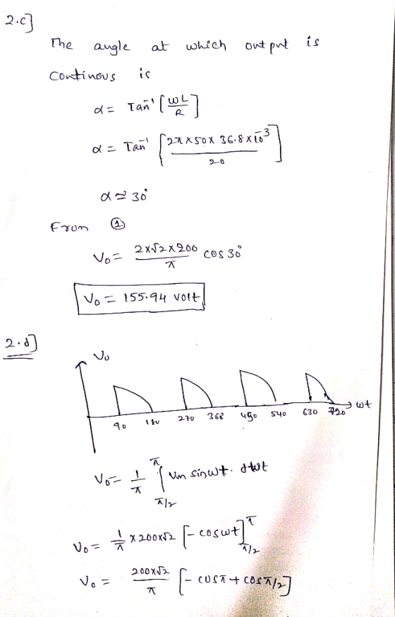
Question 2 (20 Marks): A 3-phase SCR bridge feeds a load comprising a 10Ω resistor and 1.7662 reactance connected in series, from a 3-phase 415V, 50Hz AC supply. a) For a firing angle of a (i.e. diode operation), calculate the average DC output (6...
If the load reactance is now changed to a very large series
inductance, calculate the
firing angle required to achieve a DC output load current of
20A.
with rload =10ohm and 1.76ohm reactance connected to it
Question 2 (20 Marks): A 3-phase SCR bridge feeds a load comprising a 10Ω resistor and 1.7662 reactance connected in series, from a 3-phase 415V, 50Hz AC supply. a) For a firing angle of a (i.e. diode operation), calculate the average DC output (6...
i want the answer with detales Single-Phase Controlled Rectifier Exercise Derive the expressions of the average...
 i want the answer with detales
Single-Phase Controlled Rectifier Exercise Derive the expressions of the average load voltage and current in single-phase half-wave controlled rectifiers and resistive load. Draw the waveforms of supply voltage. output voltage, output current, thyristor voltage and thyristor current Exercise In a single-phase half-wave controlled rectifier and resistive kad, it is desired to get an average load voltage of 80 V. Determine the firing angle if the ac supply voltage is 230 V. If the load...
i want the answer with detales
Single-Phase Controlled Rectifier Exercise Derive the expressions of the average load voltage and current in single-phase half-wave controlled rectifiers and resistive load. Draw the waveforms of supply voltage. output voltage, output current, thyristor voltage and thyristor current Exercise In a single-phase half-wave controlled rectifier and resistive kad, it is desired to get an average load voltage of 80 V. Determine the firing angle if the ac supply voltage is 230 V. If the load...
A single phase half wave controlled rectifier shown below operates from ideal sinusoidal source with vi...
 A single phase half wave controlled rectifier shown below
operates from ideal sinusoidal source with vi =325sinwt at 50Hz. If
the load is purely resistive, and at a certain α, the output dc
voltage is Vdc =95V, and the average
valu of the load current is 2.2A. It is required to calculate the
following:
a) The triggering angle α
b) Load resistance
c) r.m.s load current
d) dc power
is 다. Firing Circuit
A single phase half wave controlled rectifier shown below
operates from ideal sinusoidal source with vi =325sinwt at 50Hz. If
the load is purely resistive, and at a certain α, the output dc
voltage is Vdc =95V, and the average
valu of the load current is 2.2A. It is required to calculate the
following:
a) The triggering angle α
b) Load resistance
c) r.m.s load current
d) dc power
is 다. Firing Circuit
(a) Two three-phase, 400kV (rms), 50Hz, AC networks are connected together via a current-source HVDC link...
(a) Two three-phase, 400kV (rms), 50Hz, AC networks are connected together via a current-source HVDC link made up of a three-phase, 12-pulse full-wave thyristor rectifier and a three-phase, 12-pulse full-wave thyristor inverter. (i) Draw the circuit diagram for this system and explain, for the rectifier stage, how the firing delay angle may be used to control the average DC voltage. (ii) Explain the main advantages of HVDC transmission compared to AC transmission. (b) An H-Bridge converter is to be used...
Questions 1 to 3 relate to a three-phase SCR rectifier supplied from a 415 Vrms, 50 Hz ac source. For a 100 Ω resistive load, determine the peak, minimum and average load current for SCR firing angle...
 Questions 1 to 3 relate to a three-phase SCR rectifier supplied from a 415 Vrms, 50 Hz ac source. For a 100 Ω resistive load, determine the peak, minimum and average load current for SCR firing angles of: (a) a-0° (5.87 A, 5.08 A, 5.6 A) (b) α = 45° (5.67 A, 1.52 A, 3.96 A) (c) α-70° (4.5 A, 0 A, 2.0 A) How will your answers change if a very large inductance (zero resistance) is added in series...
3. A controlled single-phase fiull-wave controlled rectifier is connected in a de motor drive in Figure...
 3. A controlled single-phase fiull-wave controlled rectifier is connected in a de motor drive in Figure 4. The de motor armature inductance can be assumed large enough such that any motor curent ripple is negligible. (a) Assuming negligible supply reactance, show that the average rectifier output voltage V, in tems of the supply ms voltage E and the firing angle a, is given by 2/2E (6 marks) cos a _ (b) Given that the supply voltage is 230V, 50HZ and...
Thyristor single phase bridge rectifier hat is the rectification mode and the inversion mode (give a...
 Thyristor single phase bridge rectifier
hat is the rectification mode and the inversion mode (give a range for firing angle)? 8. Consider a single phase dual converter. what une the average output voltages Vael and Ka? Find α/ in functions) i a. 9. Draw the voltage and current oupal of single phase dual converter. (given a- 45) 10. Why is the circulation curreni neressary in the eperation of dual converter?
Thyristor single phase bridge rectifier
hat is the rectification mode and the inversion mode (give a range for firing angle)? 8. Consider a single phase dual converter. what une the average output voltages Vael and Ka? Find α/ in functions) i a. 9. Draw the voltage and current oupal of single phase dual converter. (given a- 45) 10. Why is the circulation curreni neressary in the eperation of dual converter?
T2_P1Q3 A full wave rectifier is supplied from a 100Vms Source. For a load consisting of...
 T2_P1Q3 A full wave rectifier is supplied from a 100Vms Source. For a load consisting of a 60V battery fed through a 2 Q resistor as shown in Fig. 2. i(t 2 VD(t VR(t Vs(t) Vbat VL(t) Fig. 2 (a) Sketch: the supply voltage vs(t) the rectified voltage vl(t) the voltage across the resistor vR(t) the circuit current i(t) the voltage across the diode vn(t). Determine the Peak Inverse Voltage across the diode (b)
T2_P1Q3 A full wave rectifier is...
T2_P1Q3 A full wave rectifier is supplied from a 100Vms Source. For a load consisting of a 60V battery fed through a 2 Q resistor as shown in Fig. 2. i(t 2 VD(t VR(t Vs(t) Vbat VL(t) Fig. 2 (a) Sketch: the supply voltage vs(t) the rectified voltage vl(t) the voltage across the resistor vR(t) the circuit current i(t) the voltage across the diode vn(t). Determine the Peak Inverse Voltage across the diode (b)
T2_P1Q3 A full wave rectifier is...
 b. Consider the single-phase fully controlled of thyristor bridge rectifier supplies a load consists of R-L load and Vee in series as shown in Figure Q2 (b). The parameters for this circuit are as follows: supply voltage is 120 Vrms at 60 Hz, DC voltage, Voe equal to 10 v. i. Sketch the waveforms for output voltage, thyristor current, diode current and output current (CO2: PO2 - 5 marks) Calculate the output voltage, Va at a = Tt/2. (CO2: PO2...
 can you calculate and explain why? thanks
A single-phase thyristor rectifier as 50 Hz source. The rectifier delivers a DC voltage of 150 V to a highly inductive depicted in Figure 1 is fed from a 220 V rms, 1. load with a resistive value of 10 Q. SCR, T SCR2 + is Vo SCR3 SCR T Figure 1 (a) for a delay angle component indicating its phase shift with respect to the input voltage v, Sketch the net rectifier...
can you calculate and explain why? thanks
A single-phase thyristor rectifier as 50 Hz source. The rectifier delivers a DC voltage of 150 V to a highly inductive depicted in Figure 1 is fed from a 220 V rms, 1. load with a resistive value of 10 Q. SCR, T SCR2 + is Vo SCR3 SCR T Figure 1 (a) for a delay angle component indicating its phase shift with respect to the input voltage v, Sketch the net rectifier...
 If the load reactance is now changed to a very large series
inductance, calculate the
firing angle required to achieve a DC output load current of
20A.
with rload =10ohm and 1.76ohm reactance connected to it
Question 2 (20 Marks): A 3-phase SCR bridge feeds a load comprising a 10Ω resistor and 1.7662 reactance connected in series, from a 3-phase 415V, 50Hz AC supply. a) For a firing angle of a (i.e. diode operation), calculate the average DC output (6...
If the load reactance is now changed to a very large series
inductance, calculate the
firing angle required to achieve a DC output load current of
20A.
with rload =10ohm and 1.76ohm reactance connected to it
Question 2 (20 Marks): A 3-phase SCR bridge feeds a load comprising a 10Ω resistor and 1.7662 reactance connected in series, from a 3-phase 415V, 50Hz AC supply. a) For a firing angle of a (i.e. diode operation), calculate the average DC output (6...
 i want the answer with detales
Single-Phase Controlled Rectifier Exercise Derive the expressions of the average load voltage and current in single-phase half-wave controlled rectifiers and resistive load. Draw the waveforms of supply voltage. output voltage, output current, thyristor voltage and thyristor current Exercise In a single-phase half-wave controlled rectifier and resistive kad, it is desired to get an average load voltage of 80 V. Determine the firing angle if the ac supply voltage is 230 V. If the load...
i want the answer with detales
Single-Phase Controlled Rectifier Exercise Derive the expressions of the average load voltage and current in single-phase half-wave controlled rectifiers and resistive load. Draw the waveforms of supply voltage. output voltage, output current, thyristor voltage and thyristor current Exercise In a single-phase half-wave controlled rectifier and resistive kad, it is desired to get an average load voltage of 80 V. Determine the firing angle if the ac supply voltage is 230 V. If the load...
 A single phase half wave controlled rectifier shown below
operates from ideal sinusoidal source with vi =325sinwt at 50Hz. If
the load is purely resistive, and at a certain α, the output dc
voltage is Vdc =95V, and the average
valu of the load current is 2.2A. It is required to calculate the
following:
a) The triggering angle α
b) Load resistance
c) r.m.s load current
d) dc power
is 다. Firing Circuit
A single phase half wave controlled rectifier shown below
operates from ideal sinusoidal source with vi =325sinwt at 50Hz. If
the load is purely resistive, and at a certain α, the output dc
voltage is Vdc =95V, and the average
valu of the load current is 2.2A. It is required to calculate the
following:
a) The triggering angle α
b) Load resistance
c) r.m.s load current
d) dc power
is 다. Firing Circuit
 Questions 1 to 3 relate to a three-phase SCR rectifier supplied from a 415 Vrms, 50 Hz ac source. For a 100 Ω resistive load, determine the peak, minimum and average load current for SCR firing angles of: (a) a-0° (5.87 A, 5.08 A, 5.6 A) (b) α = 45° (5.67 A, 1.52 A, 3.96 A) (c) α-70° (4.5 A, 0 A, 2.0 A) How will your answers change if a very large inductance (zero resistance) is added in series...
 3. A controlled single-phase fiull-wave controlled rectifier is connected in a de motor drive in Figure 4. The de motor armature inductance can be assumed large enough such that any motor curent ripple is negligible. (a) Assuming negligible supply reactance, show that the average rectifier output voltage V, in tems of the supply ms voltage E and the firing angle a, is given by 2/2E (6 marks) cos a _ (b) Given that the supply voltage is 230V, 50HZ and...
 Thyristor single phase bridge rectifier
hat is the rectification mode and the inversion mode (give a range for firing angle)? 8. Consider a single phase dual converter. what une the average output voltages Vael and Ka? Find α/ in functions) i a. 9. Draw the voltage and current oupal of single phase dual converter. (given a- 45) 10. Why is the circulation curreni neressary in the eperation of dual converter?
Thyristor single phase bridge rectifier
hat is the rectification mode and the inversion mode (give a range for firing angle)? 8. Consider a single phase dual converter. what une the average output voltages Vael and Ka? Find α/ in functions) i a. 9. Draw the voltage and current oupal of single phase dual converter. (given a- 45) 10. Why is the circulation curreni neressary in the eperation of dual converter?
 T2_P1Q3 A full wave rectifier is supplied from a 100Vms Source. For a load consisting of a 60V battery fed through a 2 Q resistor as shown in Fig. 2. i(t 2 VD(t VR(t Vs(t) Vbat VL(t) Fig. 2 (a) Sketch: the supply voltage vs(t) the rectified voltage vl(t) the voltage across the resistor vR(t) the circuit current i(t) the voltage across the diode vn(t). Determine the Peak Inverse Voltage across the diode (b)
T2_P1Q3 A full wave rectifier is...
T2_P1Q3 A full wave rectifier is supplied from a 100Vms Source. For a load consisting of a 60V battery fed through a 2 Q resistor as shown in Fig. 2. i(t 2 VD(t VR(t Vs(t) Vbat VL(t) Fig. 2 (a) Sketch: the supply voltage vs(t) the rectified voltage vl(t) the voltage across the resistor vR(t) the circuit current i(t) the voltage across the diode vn(t). Determine the Peak Inverse Voltage across the diode (b)
T2_P1Q3 A full wave rectifier is...
Most questions answered within 3 hours.
-
Why are polymers not typically casted into products?
asked 3 minutes ago -
When rolling a die 129 times, what is the probability of rolling
a 6 no more...
asked 19 minutes ago -
4. A call option currently sells for $7.75. It has a strike
price of $85 and...
asked 8 minutes ago -
1.
You need to prepare 10.0 liters of an acid aqueous solution with a
pH of...
asked 11 minutes ago -
Along an aggregate supply curve, if the level of output is less
than the natural level...
asked 11 minutes ago -
By 2025, annual consumption in emerging markets will total $30
trillion and contribute more than ________...
asked 16 minutes ago -
At what point does reformation cease to be a viable option for
those who are oppressed...
asked 20 minutes ago -
Place letters corresponding to amounts in the proper order for
lightest to heaviest samples:
a) 2100...
asked 25 minutes ago -
Consider the multicore processor with 6 heterogeneous cores
labelled C1, C2, C3, C4, C5, and C6....
asked 27 minutes ago -
Document system components according to standards and procedures
(Implement and hand over system components) IT administrative
asked 28 minutes ago -
The college asked 700 students if they wanted a longer spring
break and 600 students said...
asked 27 minutes ago -
Determine the temperature (in Celsius) at which 1.00 mole of an
ideal gas will have a...
asked 52 minutes ago