
Homework Answers


Add Answer to:
T2_P1Q3 A full wave rectifier is supplied from a 100Vms Source. For a load consisting of...
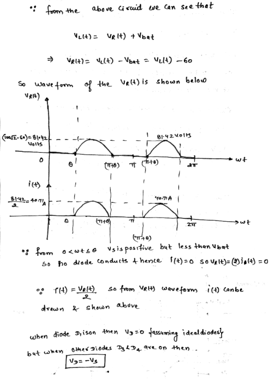
1. A half wave rectifier is supplied from a 100Vms source. For a load consisting of a 60V battery fed through a 2Ω resistor as shown in Fig. I 2Ω D+ + VR() bat Fig. 1 For the rectifier shown in Fig....
 1. A half wave rectifier is supplied from a 100Vms source. For a load consisting of a 60V battery fed through a 2Ω resistor as shown in Fig. I 2Ω D+ + VR() bat Fig. 1 For the rectifier shown in Fig. 1, determine (a) a time varying expression for the current flowing into the battery 70.7sine -30 25.1 154.9) (b) (c) the average power flow into the battery (574W) the average power dissipation in the resistor (617W) A half...
In a full wave bridge rectifier, input voltage is 110sin(2pi60t) V, Vd=0.7V. The transformer turn ratio...
In a full wave bridge rectifier, input voltage is 110sin(2pi60t) V, Vd=0.7V. The transformer turn ratio is 10:1. What is the amplitude of output voltage? What is the maximum voltage across diode which is off? For load of 5kohm, calculate C for Vr of 1V.
4.70 A full-wave bridge-rectifier circuit with a 500-22 load operates from a 120-V (rms) 60-Hz household...
 4.70 A full-wave bridge-rectifier circuit with a 500-22 load operates from a 120-V (rms) 60-Hz household supply through a 6-to-1 step-down transformer having a single Secondary winding. It uses four diodes, each of which can be modeled to have a 0.7-V drop for any current. What is the peak value of the rectified voltage across the load? For what fraction of a cycle does each diode conduct? What is the average voltage across the load? What is the average current...
A single-phase full bridge thyristor rectifier is supplied from a 200vrm 50HZ AC source, and supplies...
 A single-phase full bridge thyristor rectifier is supplied from a 200vrm 50HZ AC source, and supplies a series R-L load comprising a 202 resistance and a 36.8mH inductance 2.a. Sketch the circuit diagram for this rectifier Q2. [4 marks] [Refer to lecture notes] 2.b. Determine the maximum possible average DC voltage that can be achieved across the load resistor [4 marks] [VDC (avg) = 180V] 2.c. Determine the SCR firing angle at which the rectified output curent will just be...
A full-wave diode rectifier supplies a 30Ω resistive load from a 400Hz, 110V single-phase AC supply....
A full-wave diode rectifier supplies a 30Ω resistive load from a 400Hz, 110V single-phase AC supply. A capacitor is connected in parallel with the load. Calculate the capacitance required if the maximum peak-to-peak voltage ripple across the resistor is to be restricted to 10V. You may assume that the RC product of the resistance and capacitance will be significantly greater than the period of the AC waveform. State any other assumptions made.
3. Perform the following calculations for the full-wave rectifier with filter capacitor in Fig. 5 Determine...
 3. Perform the following calculations for the full-wave rectifier with filter capacitor in Fig. 5 Determine the maximum value of vo(f), vOpeak a. b. Determine the peak-to-peak ripple voltage, vr, peak-peak Determine the approximate average value of vo(t). You do not have to use integration. Assume the ripple waveform has an ideal sawtooth shape with each "tooth" being a right triangle having amplitude vr peak-peak as in Fig. 6 C. d. Sketch a realistic ripple waveform superimposed on the unfiltered...
6.26. Calculate the average power delivered to the load for the full-wave bridge rectifier circuit in...
 6.26. Calculate the average power delivered to the load for the full-wave bridge rectifier circuit in Figure 6.9 if the diode is ideal, Vac is sinusoidal with a peak value of 170 V, and the load resistor has a value of 100 12. AC D4 -DC 4 +DC 4 D AC RL FIGURE 6.9 Full-wave bridge rectifier circuit.
Use matlab to solve Project A half-wave diode rectifier shown in the following Fig. 1 is...
 Use matlab to solve
Project A half-wave diode rectifier shown in the following Fig. 1 is an electrical cirouit that coeverts AC voltage to DC voltage. The voltage of the source is y,Sin(utwhere -f in whicfis the frequency. The operation of the circuit is illustrated in Fig. 2 where the dashod line shows the source veltage and the solid line shows the voltage across the resistor Diode Time Fig. 1 In the first cycle, thediode is on (conductingcurrent)fromに0umi 4Atthstme thediodetums...
Use matlab to solve
Project A half-wave diode rectifier shown in the following Fig. 1 is an electrical cirouit that coeverts AC voltage to DC voltage. The voltage of the source is y,Sin(utwhere -f in whicfis the frequency. The operation of the circuit is illustrated in Fig. 2 where the dashod line shows the source veltage and the solid line shows the voltage across the resistor Diode Time Fig. 1 In the first cycle, thediode is on (conductingcurrent)fromに0umi 4Atthstme thediodetums...
Design a FULL WAVE BRIDGE RECTIFIER circuit that will: Take 120volts ac, 60 hz, sinusoidal waveform...
 Design a FULL WAVE BRIDGE RECTIFIER circuit that will:
Take 120volts ac, 60 hz, sinusoidal waveform and convert
it to a “regulated “dc value
giving 12 volts +, - 1 volt across a 2000-ohm output
load resistor with no more than 2%
ripple voltage.
You may assume:
a. An ideal power transformer as discussed in class.
b. For hand computations, you must assume a diode given by
Figure 4.8 page 185.
c. A filter capacitor sized per the textbook equation...
Design a FULL WAVE BRIDGE RECTIFIER circuit that will:
Take 120volts ac, 60 hz, sinusoidal waveform and convert
it to a “regulated “dc value
giving 12 volts +, - 1 volt across a 2000-ohm output
load resistor with no more than 2%
ripple voltage.
You may assume:
a. An ideal power transformer as discussed in class.
b. For hand computations, you must assume a diode given by
Figure 4.8 page 185.
c. A filter capacitor sized per the textbook equation...
Question 4. (a) A full-wave bridge rectifier power supply is powered from the secondary of a...
 Question 4. (a) A full-wave bridge rectifier power supply is powered from the secondary of a transformer which has a rms secondary voltage of 15.6V. The primary of the transformer is connected to a 50Hz, 230VRMS power supply. A 2700uF filter capacitor is used. A current of 1.5 Amp is drawn from the supply. (i) Sketch a schematic diagram of the setup. (ii) Calculate the mean de output voltage. Assume each power diode has a forward voltage drop of 1...
 1. A half wave rectifier is supplied from a 100Vms source. For a load consisting of a 60V battery fed through a 2Ω resistor as shown in Fig. I 2Ω D+ + VR() bat Fig. 1 For the rectifier shown in Fig. 1, determine (a) a time varying expression for the current flowing into the battery 70.7sine -30 25.1 154.9) (b) (c) the average power flow into the battery (574W) the average power dissipation in the resistor (617W) A half...
 4.70 A full-wave bridge-rectifier circuit with a 500-22 load operates from a 120-V (rms) 60-Hz household supply through a 6-to-1 step-down transformer having a single Secondary winding. It uses four diodes, each of which can be modeled to have a 0.7-V drop for any current. What is the peak value of the rectified voltage across the load? For what fraction of a cycle does each diode conduct? What is the average voltage across the load? What is the average current...
 A single-phase full bridge thyristor rectifier is supplied from a 200vrm 50HZ AC source, and supplies a series R-L load comprising a 202 resistance and a 36.8mH inductance 2.a. Sketch the circuit diagram for this rectifier Q2. [4 marks] [Refer to lecture notes] 2.b. Determine the maximum possible average DC voltage that can be achieved across the load resistor [4 marks] [VDC (avg) = 180V] 2.c. Determine the SCR firing angle at which the rectified output curent will just be...
 3. Perform the following calculations for the full-wave rectifier with filter capacitor in Fig. 5 Determine the maximum value of vo(f), vOpeak a. b. Determine the peak-to-peak ripple voltage, vr, peak-peak Determine the approximate average value of vo(t). You do not have to use integration. Assume the ripple waveform has an ideal sawtooth shape with each "tooth" being a right triangle having amplitude vr peak-peak as in Fig. 6 C. d. Sketch a realistic ripple waveform superimposed on the unfiltered...
 6.26. Calculate the average power delivered to the load for the full-wave bridge rectifier circuit in Figure 6.9 if the diode is ideal, Vac is sinusoidal with a peak value of 170 V, and the load resistor has a value of 100 12. AC D4 -DC 4 +DC 4 D AC RL FIGURE 6.9 Full-wave bridge rectifier circuit.
 Use matlab to solve
Project A half-wave diode rectifier shown in the following Fig. 1 is an electrical cirouit that coeverts AC voltage to DC voltage. The voltage of the source is y,Sin(utwhere -f in whicfis the frequency. The operation of the circuit is illustrated in Fig. 2 where the dashod line shows the source veltage and the solid line shows the voltage across the resistor Diode Time Fig. 1 In the first cycle, thediode is on (conductingcurrent)fromに0umi 4Atthstme thediodetums...
Use matlab to solve
Project A half-wave diode rectifier shown in the following Fig. 1 is an electrical cirouit that coeverts AC voltage to DC voltage. The voltage of the source is y,Sin(utwhere -f in whicfis the frequency. The operation of the circuit is illustrated in Fig. 2 where the dashod line shows the source veltage and the solid line shows the voltage across the resistor Diode Time Fig. 1 In the first cycle, thediode is on (conductingcurrent)fromに0umi 4Atthstme thediodetums...
 Design a FULL WAVE BRIDGE RECTIFIER circuit that will:
Take 120volts ac, 60 hz, sinusoidal waveform and convert
it to a “regulated “dc value
giving 12 volts +, - 1 volt across a 2000-ohm output
load resistor with no more than 2%
ripple voltage.
You may assume:
a. An ideal power transformer as discussed in class.
b. For hand computations, you must assume a diode given by
Figure 4.8 page 185.
c. A filter capacitor sized per the textbook equation...
Design a FULL WAVE BRIDGE RECTIFIER circuit that will:
Take 120volts ac, 60 hz, sinusoidal waveform and convert
it to a “regulated “dc value
giving 12 volts +, - 1 volt across a 2000-ohm output
load resistor with no more than 2%
ripple voltage.
You may assume:
a. An ideal power transformer as discussed in class.
b. For hand computations, you must assume a diode given by
Figure 4.8 page 185.
c. A filter capacitor sized per the textbook equation...
 Question 4. (a) A full-wave bridge rectifier power supply is powered from the secondary of a transformer which has a rms secondary voltage of 15.6V. The primary of the transformer is connected to a 50Hz, 230VRMS power supply. A 2700uF filter capacitor is used. A current of 1.5 Amp is drawn from the supply. (i) Sketch a schematic diagram of the setup. (ii) Calculate the mean de output voltage. Assume each power diode has a forward voltage drop of 1...
Most questions answered within 3 hours.
-
suppose there is a normally distributed population with a mean of
250 and a standard deviation...
asked 22 minutes ago -
Question Three
Suppose you as project manager are using the Waterfall
development methodology on a large...
asked 1 hour ago -
Which statement is not true about welfare in Canada?
A.Benefits typically vary based on one's ability...
asked 1 hour ago -
Please help me with FLOWCHART and UML diagram for class,
thank you!
#include <iostream>
#include <fstream>...
asked 2 hours ago -
3. Describe the “logic circuit” of the Lac operon. Which
proteins are bound or not to...
asked 2 hours ago -
Ayesha’s adjusted gross income is $60,000 in 2019. She donated a
piece of artwork with a...
asked 2 hours ago -
For Dijkstra’s shortest path algorithm:
a. Give the Big-O time for Dijkstra’s shortest path algorithm
and...
asked 2 hours ago -
Phosphorus violates the 'octet rule' in biological molecules,
forming more covalent bonds than expected based on...
asked 3 hours ago -
A 1.3 eV electron has a 10-4 probability of tunneling
through a 2.4 eV potential barrier....
asked 3 hours ago -
What is the one ingredient that is common to being successful
with all stakeholders?
profit
trust...
asked 3 hours ago -
Write an assembly language 32 bit program that reads in lines of
text by a .txt...
asked 3 hours ago -
what is the density ( in g/L) of hydrogen gas at 29 degrees C and a...
asked 3 hours ago