
Homework Answers


Add Answer to:
Procedure Load Multisim Live in a web browser and sign in. Create a new circuit. a....
Procedure Load Multisim Live in a web browser and sign in. Create a new circuit. a....
 Procedure Load Multisim Live in a web browser and sign in. Create a new circuit. a. Place the components and wire up the circuit shown in Figure 1. Note the polarity (orientation) of the DC voltage supplies (V1 and V2) for the op amp. b. ww 3k9 v1 SV PRI R1 ww V3 1k2 RL 1V 1kHz 1k0 Figure 1 Set the simulation mode to "Transient". Simulate the circuit and determine the following values c. Maximum voltage at the input...
B- Multisim Simulations: a) Create a Multisim circuit (similar to Fig.1) with the followings: 10 1....
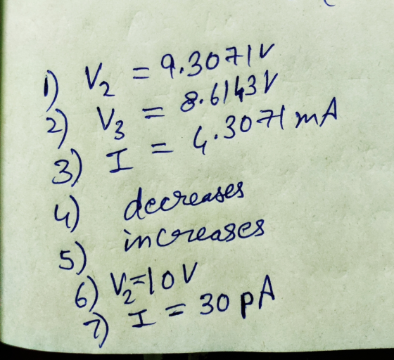
 B- Multisim Simulations: a) Create a Multisim circuit (similar to Fig.1) with the followings: 10 1. One Voltmeter measures the source voltage E and 3 Voltmeters measure V1, V2, V3. 2. Three Ammeters measure source current at A, B and C. Figure 1: Is A V1 + M R1 47002 + R2 } 5 V 62003 R3 1k02 | V3 + C
Using MULTISIM SIMULATION PLEASE!!! using multisim please Reversed Vascu Procedure II: Diode Characteristics: 1. Wire the...
 Using MULTISIM SIMULATION PLEASE!!!
using multisim please
Reversed Vascu Procedure II: Diode Characteristics: 1. Wire the circuit shown in Figure B. 3300 LA Vs Vd = (0-15V) Figure B Diode Characteristics pote Mode is defined as The dy to the dio rent through 10 3. Now reverse the diode then adjust the DC supply as shown in Table 2, Record the corresponding current and diode voltage as in step 2. Table 2 Reversed Bias Diode Characteristics Vs (volt) Va la...
Using MULTISIM SIMULATION PLEASE!!!
using multisim please
Reversed Vascu Procedure II: Diode Characteristics: 1. Wire the circuit shown in Figure B. 3300 LA Vs Vd = (0-15V) Figure B Diode Characteristics pote Mode is defined as The dy to the dio rent through 10 3. Now reverse the diode then adjust the DC supply as shown in Table 2, Record the corresponding current and diode voltage as in step 2. Table 2 Reversed Bias Diode Characteristics Vs (volt) Va la...
02 +Vo D3 Rgare 18 Circuit for Problem 1 Analysis 1. Copy the circuit of Figure 1.8 and sketch the ow of pesitive curment throughout the entire circuit for o>0. Repeat for n ce 2....
 02 +Vo D3 Rgare 18 Circuit for Problem 1 Analysis 1. Copy the circuit of Figure 1.8 and sketch the ow of pesitive curment throughout the entire circuit for o>0. Repeat for n ce 2. Plot two periods of nlt) and s) for each of the thee input wave shown in Figune 17 on page 37 fom output t (a) Feak value, and b) Eflective DC value, also known as RMS value NotTE These and are therefore optional 4. Determine...
do the part on red please. 1. Validate conclusions regarding the behavior of inductors in transient...
 do the part on red please.
1. Validate conclusions regarding the behavior of inductors in transient and steady-state DC network. 2. Verify basic equations for determining the total induction in series, parallel and series-parallel circuits. 3. Use simulation software to understand circuit characteristics. EQUIPMENT REQUIRED: Multisim tool. PROCEDURES: Part 1. Series RL Circuits Use the circuit of Figure 4 (pick RL=202). a. Calculate the steady-state values of IL and VL. IL = 20.4 mA VL = _0.408_V IL=10 / (470...
do the part on red please.
1. Validate conclusions regarding the behavior of inductors in transient and steady-state DC network. 2. Verify basic equations for determining the total induction in series, parallel and series-parallel circuits. 3. Use simulation software to understand circuit characteristics. EQUIPMENT REQUIRED: Multisim tool. PROCEDURES: Part 1. Series RL Circuits Use the circuit of Figure 4 (pick RL=202). a. Calculate the steady-state values of IL and VL. IL = 20.4 mA VL = _0.408_V IL=10 / (470...
nde) Figare 18 Circuit for Problem 15 Analysis 1. Plot the input and output vollage wavefoems nlt) and lt) as wel as the capacitor current iclt) for the input wavelorm shown in Fig ure 1....
 nde) Figare 18 Circuit for Problem 15 Analysis 1. Plot the input and output vollage wavefoems nlt) and lt) as wel as the capacitor current iclt) for the input wavelorm shown in Fig ure 1.10 on the next page, Assume the capacitoris initially discharged 2 Determine the following numerical descriptors for lf) and iclf (a) Voltage values of t) at times-250, 650, and 960ms. (b) Peak capacitor current t Discass the relationship between the plots of the capacitor current ic(t)...
Lab Procedure: Part 1: Source Free RC Circuit V(t) ilts C3 (R3 21ko 1uF IC=10V a)...
 Lab Procedure: Part 1: Source Free RC Circuit V(t) ilts C3 (R3 21ko 1uF IC=10V a) For the circuit shown above, provide the equation and calculate the following: 1. The source free equation for V(t) for V(O)= 10 volts 2. The equation for it) 3. V(t) and i(t) for t = t (one time constant) b) Now, enter the circuit using Multisim Schematic Capture. c) Simulate using Transient mode with a graphical output and verify graphical results with your calculations....
once simulated can tou explain what the diodes are doing ... please explain good thank you...
 once simulated can tou explain what the diodes are doing ...
please explain good thank you
Problem 1: Voltage Limiting 1.1. Simulate the following simple resistor-diode circuit (shown on the left in Figure 1) R1 V out V1 ZD1 VOFF 0 VAMPL 3V FREQ 1KHZ 0.7 D1N4148 Figure Let V(in) be a 1KHZ VSIN with an amplitude of 3V. RI is 1KO. Lowest node voltage is ground. (1.1a) Set up PSPICE Transient and plot both V(in) and V(out) on the...
once simulated can tou explain what the diodes are doing ...
please explain good thank you
Problem 1: Voltage Limiting 1.1. Simulate the following simple resistor-diode circuit (shown on the left in Figure 1) R1 V out V1 ZD1 VOFF 0 VAMPL 3V FREQ 1KHZ 0.7 D1N4148 Figure Let V(in) be a 1KHZ VSIN with an amplitude of 3V. RI is 1KO. Lowest node voltage is ground. (1.1a) Set up PSPICE Transient and plot both V(in) and V(out) on the...
uestion # R1 R2 10? 16? S1 V1 10V R4 90? R5 9? 2A R3 2?...
 uestion # R1 R2 10? 16? S1 V1 10V R4 90? R5 9? 2A R3 2? For the circuit shown in the above figure: a) Calculate the voltage across the switch S1 when the switch is open. Determine which node has higher voltage "d" or "c". Show all the steps of your work. Values without the work steps are ZERO points. b) Calculate the current through the R2 resistor when the switch S1 is closed. Does this current flow from...
multisim help Part II: Capacitors in AC Circuits In this part, you will determine the impedance...
 multisim help
Part II: Capacitors in AC Circuits In this part, you will determine the impedance of the circuit at various frequencies. The capacitive reactance is calculated using Xc = Vc/Ic 1- Construct the circuit of Figure 9.2. Connect meters to measure voltage and current. R1 mA 1kohm C1 AC 3.3uF Figure 9.2-Circuit to Determine Capacitive Reactance 2- Set the voltage to 6Vrms at 60Hz. Measure and record values in Table 9.3. Calculate reactance using Xc = 1/(2nf C) and...
multisim help
Part II: Capacitors in AC Circuits In this part, you will determine the impedance of the circuit at various frequencies. The capacitive reactance is calculated using Xc = Vc/Ic 1- Construct the circuit of Figure 9.2. Connect meters to measure voltage and current. R1 mA 1kohm C1 AC 3.3uF Figure 9.2-Circuit to Determine Capacitive Reactance 2- Set the voltage to 6Vrms at 60Hz. Measure and record values in Table 9.3. Calculate reactance using Xc = 1/(2nf C) and...
 Procedure Load Multisim Live in a web browser and sign in. Create a new circuit. a. Place the components and wire up the circuit shown in Figure 1. Note the polarity (orientation) of the DC voltage supplies (V1 and V2) for the op amp. b. ww 3k9 v1 SV PRI R1 ww V3 1k2 RL 1V 1kHz 1k0 Figure 1 Set the simulation mode to "Transient". Simulate the circuit and determine the following values c. Maximum voltage at the input...
 B- Multisim Simulations: a) Create a Multisim circuit (similar to Fig.1) with the followings: 10 1. One Voltmeter measures the source voltage E and 3 Voltmeters measure V1, V2, V3. 2. Three Ammeters measure source current at A, B and C. Figure 1: Is A V1 + M R1 47002 + R2 } 5 V 62003 R3 1k02 | V3 + C
 Using MULTISIM SIMULATION PLEASE!!!
using multisim please
Reversed Vascu Procedure II: Diode Characteristics: 1. Wire the circuit shown in Figure B. 3300 LA Vs Vd = (0-15V) Figure B Diode Characteristics pote Mode is defined as The dy to the dio rent through 10 3. Now reverse the diode then adjust the DC supply as shown in Table 2, Record the corresponding current and diode voltage as in step 2. Table 2 Reversed Bias Diode Characteristics Vs (volt) Va la...
Using MULTISIM SIMULATION PLEASE!!!
using multisim please
Reversed Vascu Procedure II: Diode Characteristics: 1. Wire the circuit shown in Figure B. 3300 LA Vs Vd = (0-15V) Figure B Diode Characteristics pote Mode is defined as The dy to the dio rent through 10 3. Now reverse the diode then adjust the DC supply as shown in Table 2, Record the corresponding current and diode voltage as in step 2. Table 2 Reversed Bias Diode Characteristics Vs (volt) Va la...
 02 +Vo D3 Rgare 18 Circuit for Problem 1 Analysis 1. Copy the circuit of Figure 1.8 and sketch the ow of pesitive curment throughout the entire circuit for o>0. Repeat for n ce 2. Plot two periods of nlt) and s) for each of the thee input wave shown in Figune 17 on page 37 fom output t (a) Feak value, and b) Eflective DC value, also known as RMS value NotTE These and are therefore optional 4. Determine...
 do the part on red please.
1. Validate conclusions regarding the behavior of inductors in transient and steady-state DC network. 2. Verify basic equations for determining the total induction in series, parallel and series-parallel circuits. 3. Use simulation software to understand circuit characteristics. EQUIPMENT REQUIRED: Multisim tool. PROCEDURES: Part 1. Series RL Circuits Use the circuit of Figure 4 (pick RL=202). a. Calculate the steady-state values of IL and VL. IL = 20.4 mA VL = _0.408_V IL=10 / (470...
do the part on red please.
1. Validate conclusions regarding the behavior of inductors in transient and steady-state DC network. 2. Verify basic equations for determining the total induction in series, parallel and series-parallel circuits. 3. Use simulation software to understand circuit characteristics. EQUIPMENT REQUIRED: Multisim tool. PROCEDURES: Part 1. Series RL Circuits Use the circuit of Figure 4 (pick RL=202). a. Calculate the steady-state values of IL and VL. IL = 20.4 mA VL = _0.408_V IL=10 / (470...
 nde) Figare 18 Circuit for Problem 15 Analysis 1. Plot the input and output vollage wavefoems nlt) and lt) as wel as the capacitor current iclt) for the input wavelorm shown in Fig ure 1.10 on the next page, Assume the capacitoris initially discharged 2 Determine the following numerical descriptors for lf) and iclf (a) Voltage values of t) at times-250, 650, and 960ms. (b) Peak capacitor current t Discass the relationship between the plots of the capacitor current ic(t)...
 Lab Procedure: Part 1: Source Free RC Circuit V(t) ilts C3 (R3 21ko 1uF IC=10V a) For the circuit shown above, provide the equation and calculate the following: 1. The source free equation for V(t) for V(O)= 10 volts 2. The equation for it) 3. V(t) and i(t) for t = t (one time constant) b) Now, enter the circuit using Multisim Schematic Capture. c) Simulate using Transient mode with a graphical output and verify graphical results with your calculations....
 once simulated can tou explain what the diodes are doing ...
please explain good thank you
Problem 1: Voltage Limiting 1.1. Simulate the following simple resistor-diode circuit (shown on the left in Figure 1) R1 V out V1 ZD1 VOFF 0 VAMPL 3V FREQ 1KHZ 0.7 D1N4148 Figure Let V(in) be a 1KHZ VSIN with an amplitude of 3V. RI is 1KO. Lowest node voltage is ground. (1.1a) Set up PSPICE Transient and plot both V(in) and V(out) on the...
once simulated can tou explain what the diodes are doing ...
please explain good thank you
Problem 1: Voltage Limiting 1.1. Simulate the following simple resistor-diode circuit (shown on the left in Figure 1) R1 V out V1 ZD1 VOFF 0 VAMPL 3V FREQ 1KHZ 0.7 D1N4148 Figure Let V(in) be a 1KHZ VSIN with an amplitude of 3V. RI is 1KO. Lowest node voltage is ground. (1.1a) Set up PSPICE Transient and plot both V(in) and V(out) on the...
 uestion # R1 R2 10? 16? S1 V1 10V R4 90? R5 9? 2A R3 2? For the circuit shown in the above figure: a) Calculate the voltage across the switch S1 when the switch is open. Determine which node has higher voltage "d" or "c". Show all the steps of your work. Values without the work steps are ZERO points. b) Calculate the current through the R2 resistor when the switch S1 is closed. Does this current flow from...
 multisim help
Part II: Capacitors in AC Circuits In this part, you will determine the impedance of the circuit at various frequencies. The capacitive reactance is calculated using Xc = Vc/Ic 1- Construct the circuit of Figure 9.2. Connect meters to measure voltage and current. R1 mA 1kohm C1 AC 3.3uF Figure 9.2-Circuit to Determine Capacitive Reactance 2- Set the voltage to 6Vrms at 60Hz. Measure and record values in Table 9.3. Calculate reactance using Xc = 1/(2nf C) and...
multisim help
Part II: Capacitors in AC Circuits In this part, you will determine the impedance of the circuit at various frequencies. The capacitive reactance is calculated using Xc = Vc/Ic 1- Construct the circuit of Figure 9.2. Connect meters to measure voltage and current. R1 mA 1kohm C1 AC 3.3uF Figure 9.2-Circuit to Determine Capacitive Reactance 2- Set the voltage to 6Vrms at 60Hz. Measure and record values in Table 9.3. Calculate reactance using Xc = 1/(2nf C) and...
Most questions answered within 3 hours.
-
Derive the long wavelength limit of the Planck energy density
distribution
asked 5 minutes ago -
Phosphorous + bromine = phosphorous tribromide. If 35.0 g of
bromine are reacted and 27.9 grams...
asked 15 minutes ago -
Calculate the pH of each of the following solutions.
0.50 M HBr
3.1×10⁻⁴ M KOH
4.2×10⁻⁵...
asked 3 hours ago -
For the year ended December 31, Depot Max’s cost of merchandise
sold was $85,600. Inventory at the...
asked 3 hours ago -
Week 10 - Professional Memo Assignment
Professional Memo Assignment
Your mission for this week, should you...
asked 3 hours ago -
Write a Python program that stores the data for each
player on the team, and it...
asked 3 hours ago -
In
the last 3 months, mike never knows when he is going to get his
allowance...
asked 4 hours ago -
Is Ca(OH)2 a Bronsted base, Lewis base, or both? Why?
asked 4 hours ago -
1A- Why don’t voters complain about U.S. tariffs on imported
sugar?
Because sugar is only a...
asked 4 hours ago -
Cash Payback Period
Primera Banco is evaluating two capital investment proposals for
a drive-up ATM kiosk,...
asked 4 hours ago -
Create a button in Swift (Xcode) that will create a charge,
create a charge using Stripe's...
asked 4 hours ago -
The reaction rate of CO and NO2 in the reaction
CO(g) + NO2(g) → CO2(g) +...
asked 4 hours ago