In a full wave bridge rectifier, input voltage is 110sin(2pi60t) V, Vd=0.7V. The transformer turn ratio...
Homework Answers
Answer:
A Bridge rectifier is an Alternating Current (AC) to Direct Current (DC) converter that rectifies mains AC input to DC output. Bridge Rectifiers are widely used in power supplies that provide necessary DC voltage for the electronic components or devices.


Add Answer to:
In
a full wave bridge rectifier, input voltage is 110sin(2pi60t) V,
Vd=0.7V. The transformer turn ratio...
4.70 A full-wave bridge-rectifier circuit with a 500-22 load operates from a 120-V (rms) 60-Hz household...
 4.70 A full-wave bridge-rectifier circuit with a 500-22 load operates from a 120-V (rms) 60-Hz household supply through a 6-to-1 step-down transformer having a single Secondary winding. It uses four diodes, each of which can be modeled to have a 0.7-V drop for any current. What is the peak value of the rectified voltage across the load? For what fraction of a cycle does each diode conduct? What is the average voltage across the load? What is the average current...
3. For the regulated power supply shown in Figure 5-3, which is a full-wave bridge rectifier...
 3. For the regulated power supply shown in Figure 5-3, which is a full-wave bridge rectifier containing ter combined with a Zener diode voltage regulator, determine the load voltage VI, load current Ir, source current Is, Zener current Iz and the ripple voltage at the input and output of the regulator, and r(p-p)y respectively, and the ripple frequency fr a fil- VL Ir. Is Iz=. (d-4)1a Ur(p-P) Is V' 1N4002GP Vout = VL + Iz IL 100 V2 120 V...
Design a FULL WAVE BRIDGE RECTIFIER circuit that will: Take 120volts ac, 60 hz, sinusoidal waveform...
 Design a FULL WAVE BRIDGE RECTIFIER circuit that will:
Take 120volts ac, 60 hz, sinusoidal waveform and convert
it to a “regulated “dc value
giving 12 volts +, - 1 volt across a 2000-ohm output
load resistor with no more than 2%
ripple voltage.
You may assume:
a. An ideal power transformer as discussed in class.
b. For hand computations, you must assume a diode given by
Figure 4.8 page 185.
c. A filter capacitor sized per the textbook equation...
Design a FULL WAVE BRIDGE RECTIFIER circuit that will:
Take 120volts ac, 60 hz, sinusoidal waveform and convert
it to a “regulated “dc value
giving 12 volts +, - 1 volt across a 2000-ohm output
load resistor with no more than 2%
ripple voltage.
You may assume:
a. An ideal power transformer as discussed in class.
b. For hand computations, you must assume a diode given by
Figure 4.8 page 185.
c. A filter capacitor sized per the textbook equation...
T2_P1Q3 A full wave rectifier is supplied from a 100Vms Source. For a load consisting of...
 T2_P1Q3 A full wave rectifier is supplied from a 100Vms Source. For a load consisting of a 60V battery fed through a 2 Q resistor as shown in Fig. 2. i(t 2 VD(t VR(t Vs(t) Vbat VL(t) Fig. 2 (a) Sketch: the supply voltage vs(t) the rectified voltage vl(t) the voltage across the resistor vR(t) the circuit current i(t) the voltage across the diode vn(t). Determine the Peak Inverse Voltage across the diode (b)
T2_P1Q3 A full wave rectifier is...
T2_P1Q3 A full wave rectifier is supplied from a 100Vms Source. For a load consisting of a 60V battery fed through a 2 Q resistor as shown in Fig. 2. i(t 2 VD(t VR(t Vs(t) Vbat VL(t) Fig. 2 (a) Sketch: the supply voltage vs(t) the rectified voltage vl(t) the voltage across the resistor vR(t) the circuit current i(t) the voltage across the diode vn(t). Determine the Peak Inverse Voltage across the diode (b)
T2_P1Q3 A full wave rectifier is...
w A ovo 3. (15 pts) The input Vg to the rectifier circuit on the right...
 w A ovo 3. (15 pts) The input Vg to the rectifier circuit on the right is a sinusoidal signal of amplitude 4V, as shown below. Use the 0.7V voltage drop model for the diode. a) Determine the maximum and minimum values of the output voltage V across load resistor RL. b) Determine the conduction angle. c) Determine the percent conduction. 10022 {RL 2002 3. (15 pts) The input to the rectifier circuit on the right is sinusoidal signal of...
3. Consider the full-wave bridge rectifier circuit shown below. The full-wave bridge is made using silicon...
 3. Consider the full-wave bridge rectifier circuit shown below. The full-wave bridge is made using silicon diodes. 120V 15V 120 V(ms) n 60 Hz 752 Vout a. Find the maximum value of VoUT, and the voltage rating for the capacitor assuming a 50% margin of safety. b. Choose the capacitance of the filter capacitor for a peak-to-peak ripple of 1V, and determine the corresponding peak diode current. What is the frequency of the ripple voltage? c. Now suppose the filter...
3. A full wave rectifier bridge has a input voltage of 120Cos(1207nt) and the output of...
 3. A full wave rectifier bridge has a input voltage of 120Cos(1207nt) and the output of the rectifier is given by |120Cos(120nt)|. Suppose this rectifier output is connected to a series and L 7.95 mH.Then, find the Fourier series of the output current 6. Also, tabulate the rms RL load with R 4 waveform up to n = phasor voltage, impedance and rms phasor current for frequency values of 0, 120 ,240, and 360 Hz
1) A classical rectifier uses a standard 120 V/25.2 V 60 Hz transformer. What ideal output...
 1) A classical rectifier uses a standard 120 V/25.2 V 60 Hz transformer. What ideal output DC voltage will result if a single-phase full-wave diode bridge is used with a large capacitor and the input is exactly 120 Vrms? Assume each diode's forward voltage drop is 1 V. Design a capacitor if the load is 50 W and the voltage ripple is 1 V peak-peak?
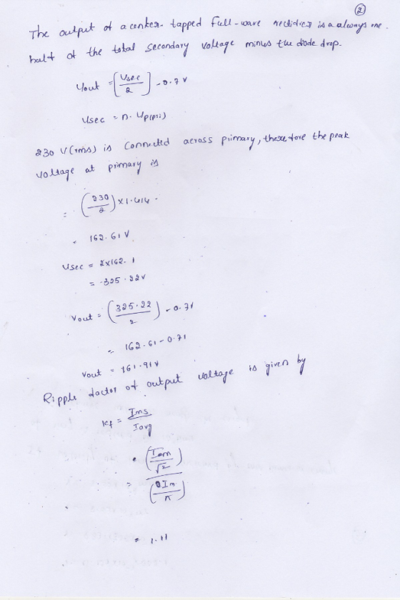
It is required to use a FULL-wave rectifier to design a dc power supply that provides...
It is required to use a FULL-wave rectifier to design a dc power supply that provides an average dc output voltage of 15 V. A maximum ripple voltage of ±1 V is allowed on the output voltage. The output voltage will feed a load resistance of 250 Ω. Assume a sinusoidal input voltage with the frequency of 60 Hz. Do not include a Zener diode in your design. (Assume V_D0)* = 0.7 V). a) Draw the circuit diagram. b) Calculate...
Question 2 of 9 Question 2 12 points Saved A full-wave bridge rectifier has 60 Hz...
 Question 2 of 9 Question 2 12 points Saved A full-wave bridge rectifier has 60 Hz input signal and the voltage signal applied at its input (secondary voltage of transformer) is at 12V rms. If the voltage drop across a diode is 0.6V and the load resistance is 10 kOhms, determine the required capacitance value to limit the ripple value to 0.1V. Choose the value closest the what you have found. 41.7 microfarad 13.14 microfarad 417 microfarad 131.4 microfarad -...
 4.70 A full-wave bridge-rectifier circuit with a 500-22 load operates from a 120-V (rms) 60-Hz household supply through a 6-to-1 step-down transformer having a single Secondary winding. It uses four diodes, each of which can be modeled to have a 0.7-V drop for any current. What is the peak value of the rectified voltage across the load? For what fraction of a cycle does each diode conduct? What is the average voltage across the load? What is the average current...
 3. For the regulated power supply shown in Figure 5-3, which is a full-wave bridge rectifier containing ter combined with a Zener diode voltage regulator, determine the load voltage VI, load current Ir, source current Is, Zener current Iz and the ripple voltage at the input and output of the regulator, and r(p-p)y respectively, and the ripple frequency fr a fil- VL Ir. Is Iz=. (d-4)1a Ur(p-P) Is V' 1N4002GP Vout = VL + Iz IL 100 V2 120 V...
 Design a FULL WAVE BRIDGE RECTIFIER circuit that will:
Take 120volts ac, 60 hz, sinusoidal waveform and convert
it to a “regulated “dc value
giving 12 volts +, - 1 volt across a 2000-ohm output
load resistor with no more than 2%
ripple voltage.
You may assume:
a. An ideal power transformer as discussed in class.
b. For hand computations, you must assume a diode given by
Figure 4.8 page 185.
c. A filter capacitor sized per the textbook equation...
Design a FULL WAVE BRIDGE RECTIFIER circuit that will:
Take 120volts ac, 60 hz, sinusoidal waveform and convert
it to a “regulated “dc value
giving 12 volts +, - 1 volt across a 2000-ohm output
load resistor with no more than 2%
ripple voltage.
You may assume:
a. An ideal power transformer as discussed in class.
b. For hand computations, you must assume a diode given by
Figure 4.8 page 185.
c. A filter capacitor sized per the textbook equation...
 T2_P1Q3 A full wave rectifier is supplied from a 100Vms Source. For a load consisting of a 60V battery fed through a 2 Q resistor as shown in Fig. 2. i(t 2 VD(t VR(t Vs(t) Vbat VL(t) Fig. 2 (a) Sketch: the supply voltage vs(t) the rectified voltage vl(t) the voltage across the resistor vR(t) the circuit current i(t) the voltage across the diode vn(t). Determine the Peak Inverse Voltage across the diode (b)
T2_P1Q3 A full wave rectifier is...
T2_P1Q3 A full wave rectifier is supplied from a 100Vms Source. For a load consisting of a 60V battery fed through a 2 Q resistor as shown in Fig. 2. i(t 2 VD(t VR(t Vs(t) Vbat VL(t) Fig. 2 (a) Sketch: the supply voltage vs(t) the rectified voltage vl(t) the voltage across the resistor vR(t) the circuit current i(t) the voltage across the diode vn(t). Determine the Peak Inverse Voltage across the diode (b)
T2_P1Q3 A full wave rectifier is...
 w A ovo 3. (15 pts) The input Vg to the rectifier circuit on the right is a sinusoidal signal of amplitude 4V, as shown below. Use the 0.7V voltage drop model for the diode. a) Determine the maximum and minimum values of the output voltage V across load resistor RL. b) Determine the conduction angle. c) Determine the percent conduction. 10022 {RL 2002 3. (15 pts) The input to the rectifier circuit on the right is sinusoidal signal of...
 3. Consider the full-wave bridge rectifier circuit shown below. The full-wave bridge is made using silicon diodes. 120V 15V 120 V(ms) n 60 Hz 752 Vout a. Find the maximum value of VoUT, and the voltage rating for the capacitor assuming a 50% margin of safety. b. Choose the capacitance of the filter capacitor for a peak-to-peak ripple of 1V, and determine the corresponding peak diode current. What is the frequency of the ripple voltage? c. Now suppose the filter...
 3. A full wave rectifier bridge has a input voltage of 120Cos(1207nt) and the output of the rectifier is given by |120Cos(120nt)|. Suppose this rectifier output is connected to a series and L 7.95 mH.Then, find the Fourier series of the output current 6. Also, tabulate the rms RL load with R 4 waveform up to n = phasor voltage, impedance and rms phasor current for frequency values of 0, 120 ,240, and 360 Hz
 1) A classical rectifier uses a standard 120 V/25.2 V 60 Hz transformer. What ideal output DC voltage will result if a single-phase full-wave diode bridge is used with a large capacitor and the input is exactly 120 Vrms? Assume each diode's forward voltage drop is 1 V. Design a capacitor if the load is 50 W and the voltage ripple is 1 V peak-peak?
 Question 2 of 9 Question 2 12 points Saved A full-wave bridge rectifier has 60 Hz input signal and the voltage signal applied at its input (secondary voltage of transformer) is at 12V rms. If the voltage drop across a diode is 0.6V and the load resistance is 10 kOhms, determine the required capacitance value to limit the ripple value to 0.1V. Choose the value closest the what you have found. 41.7 microfarad 13.14 microfarad 417 microfarad 131.4 microfarad -...
Most questions answered within 3 hours.
-
Question Three
Suppose you as project manager are using the Waterfall
development methodology on a large...
asked 30 minutes ago -
Which statement is not true about welfare in Canada?
A.Benefits typically vary based on one's ability...
asked 1 hour ago -
Please help me with FLOWCHART and UML diagram for class,
thank you!
#include <iostream>
#include <fstream>...
asked 1 hour ago -
3. Describe the “logic circuit” of the Lac operon. Which
proteins are bound or not to...
asked 1 hour ago -
Ayesha’s adjusted gross income is $60,000 in 2019. She donated a
piece of artwork with a...
asked 1 hour ago -
For Dijkstra’s shortest path algorithm:
a. Give the Big-O time for Dijkstra’s shortest path algorithm
and...
asked 2 hours ago -
Phosphorus violates the 'octet rule' in biological molecules,
forming more covalent bonds than expected based on...
asked 2 hours ago -
A 1.3 eV electron has a 10-4 probability of tunneling
through a 2.4 eV potential barrier....
asked 2 hours ago -
What is the one ingredient that is common to being successful
with all stakeholders?
profit
trust...
asked 2 hours ago -
Write an assembly language 32 bit program that reads in lines of
text by a .txt...
asked 2 hours ago -
what is the density ( in g/L) of hydrogen gas at 29 degrees C and a...
asked 2 hours ago -
5-6. You are considering three investment alternatives for some
spare cash: Old Reliable Corporation stock (A1),...
asked 2 hours ago