![15V 5a {su 13A 350 1) Calculate the power delivered by the 5A source using the following techniques: a. [10] Using nodal anal](http://img.homeworklib.com/questions/523a3330-be21-11eb-8b40-7184b6c2935b.png?x-oss-process=image/resize,w_560)
Homework Answers


Add Answer to:
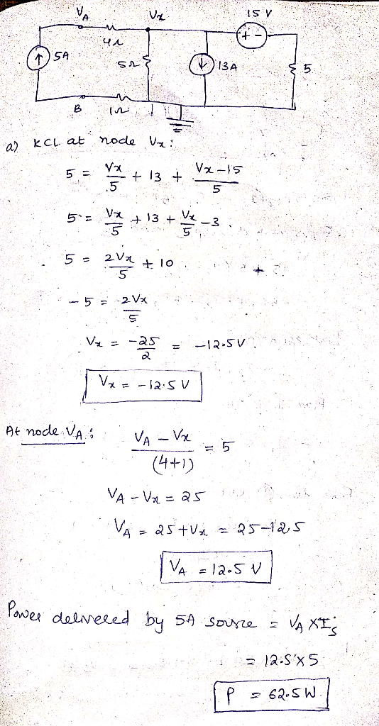
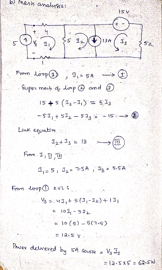
15V 5a {su 13A 350 1) Calculate the power delivered by the 5A source using the...
Part B. Wheatstone Bridge Circuit with a Current Source Is R5 R1 R2 Is RL R3 R4 For the circuit a...
 Part B. Wheatstone Bridge Circuit with a Current Source Is R5 R1 R2 Is RL R3 R4 For the circuit as shown below, given that R1-20 Ω,R2= 12 Ω, R3-18 Ω, R4= 20 Ω, R5= 9 Ω , R.-3 ΩΊ,-15 A. I. Wheatstone Bridge Circuit Analysis (a) Determining the load voltage VL-Vab for the Wheatstone bridge circuit with LTspice. Subrnit Answer Tries 0/3 (b) Determining the load current I following from a to b for the Wheatstone bridge circuit with...
*P2.66. Determine the value of V2 and the power delivered by the source in the circuit...
 *P2.66. Determine the value of V2 and the power delivered by the source in the circuit of Figure P2.24 by using mesh-current analysis. 12 Ω 25 Ω υ, = 12v 10 Ωξ η ξ30Ω ξss 6 Ω
Calculate the current through and voltage across each circuit element using Mesh Analysis Determine the current throug...
 Calculate the current through and voltage across each circuit
element using Mesh Analysis
Determine the current through and voltage across each circuit
element using Nodal Analysis
Find the Thevenin equivalent circuit for the network external
to the resistor R5 and use it to calculate the voltage
across as well as the current through the resistor
R5
Find the Norton equivalent circuit for the network external to
the resistor R5 and employ it to compute the voltage
across as well as...
Calculate the current through and voltage across each circuit
element using Mesh Analysis
Determine the current through and voltage across each circuit
element using Nodal Analysis
Find the Thevenin equivalent circuit for the network external
to the resistor R5 and use it to calculate the voltage
across as well as the current through the resistor
R5
Find the Norton equivalent circuit for the network external to
the resistor R5 and employ it to compute the voltage
across as well as...
I JUST NEED THE CORRECT ANSWER NO NEED FOR JUSTIFICATION Question 1 Not yet answered Marked...
 I JUST NEED THE CORRECT ANSWER NO NEED FOR JUSTIFICATION
Question 1 Not yet answered Marked out of 8.00 Flag question Thevenin resistance of a circuit containing only independent sources is found by then calculating the resistance seen from the terminals of the circuit Select one: a. Opening all current sources b. Shorting all voltage sources c. Opening all voltage sources and shorting all current sources d. Shorting all voltage sources and opening all current sources Question 2 Not yet...
I JUST NEED THE CORRECT ANSWER NO NEED FOR JUSTIFICATION
Question 1 Not yet answered Marked out of 8.00 Flag question Thevenin resistance of a circuit containing only independent sources is found by then calculating the resistance seen from the terminals of the circuit Select one: a. Opening all current sources b. Shorting all voltage sources c. Opening all voltage sources and shorting all current sources d. Shorting all voltage sources and opening all current sources Question 2 Not yet...
R1 C1 HH The V1 R2 11 R3 circuit shown is a simplified representation of a...
 R1 C1 HH The V1 R2 11 R3 circuit shown is a simplified representation of a small signal transistor amplifier circuit. The AC input voltage is V1, with angular frequency w. The current through R2, is It. The dependent current source, 11, has value 100 IV. Let R1 = 500, and R2 = 1000. The load resistor, R3 has a value that is selectable by a design engineer. Let C1 = 10 pF, and L1 = 1 uH. (For reference,...
EE 282-Circuit I Pre-Lab 9 Maximum Power Transfer Theorem Name Concepts: In this pre-lab we will ...
 EE 282-Circuit I Pre-Lab 9 Maximum Power Transfer Theorem Name Concepts: In this pre-lab we will be leaming about Maximum Power Transfer Theorem. Maximum power is transferred to the load when the load resistance equals the thexenin equivalent, and we carry out the analysis using Thevenin's equivalent circuit. In order to do this, first build the following circuit on Mutism. 1 R1 5.1k0 R3 2 V1 R2 8kQ 6.8㏀ Fig. 1 Part 1: To find the Thevenin equivalent resistance, we...
Due Date: 10/27/2019 EHB211E Basics of Electrical Circuits HOMEWORK 2 For the PSpice solutions, provide the...
 Due Date: 10/27/2019 EHB211E Basics of Electrical Circuits HOMEWORK 2 For the PSpice solutions, provide the schematic showing the voltage and current values and the output file. )For the bridge network in Figure 1, find i using mesh analysis. Also, obtain and show these values using PSpice program. 2 k2 ww- 6 k0 6 kn 2 ka 56 V ww 4 kn 4 k0 Figure 1 2) Find V1 and V2 using nodal analysis in Figure 2. Also, obtain and...
OUESTION 1 Anna is designing an audio amplifier for her headphones. She wants to calculate the real DC gain of the ampl...
 OUESTION 1 Anna is designing an audio amplifier for her headphones. She wants to calculate the real DC gain of the amplifier before putting music through it to make sure it won't destroy her headphones. She has setup a test circuit of the non-inverting amplifier shown below. She has used a cheap poor quality op-amp where the input resistance is 1 kQ, the output resistance is 4 Q and the open loop gain is 100xvin 2Q2 ww 4 2 V...
1. Why can the DSO only measure node voltages when the Function Generator is the power supply in ...
 1. Why can the DSO only measure node voltages when the Function Generator is the power supply in a circuit (unless it is using a current probe)? 2. Consider Figure 1. According to the calculations in the lab handout, if Z-1kΩ +/6914, then the phase difference (фи-фі) between u(t) and i (t) is 34.6". a. If this v(t) and i(t) were displayed on a DSO (v(t) being a node voltage and using a current probe for i(t) as shown in...
 Part B. Wheatstone Bridge Circuit with a Current Source Is R5 R1 R2 Is RL R3 R4 For the circuit as shown below, given that R1-20 Ω,R2= 12 Ω, R3-18 Ω, R4= 20 Ω, R5= 9 Ω , R.-3 ΩΊ,-15 A. I. Wheatstone Bridge Circuit Analysis (a) Determining the load voltage VL-Vab for the Wheatstone bridge circuit with LTspice. Subrnit Answer Tries 0/3 (b) Determining the load current I following from a to b for the Wheatstone bridge circuit with...
 *P2.66. Determine the value of V2 and the power delivered by the source in the circuit of Figure P2.24 by using mesh-current analysis. 12 Ω 25 Ω υ, = 12v 10 Ωξ η ξ30Ω ξss 6 Ω
 Calculate the current through and voltage across each circuit
element using Mesh Analysis
Determine the current through and voltage across each circuit
element using Nodal Analysis
Find the Thevenin equivalent circuit for the network external
to the resistor R5 and use it to calculate the voltage
across as well as the current through the resistor
R5
Find the Norton equivalent circuit for the network external to
the resistor R5 and employ it to compute the voltage
across as well as...
Calculate the current through and voltage across each circuit
element using Mesh Analysis
Determine the current through and voltage across each circuit
element using Nodal Analysis
Find the Thevenin equivalent circuit for the network external
to the resistor R5 and use it to calculate the voltage
across as well as the current through the resistor
R5
Find the Norton equivalent circuit for the network external to
the resistor R5 and employ it to compute the voltage
across as well as...
 I JUST NEED THE CORRECT ANSWER NO NEED FOR JUSTIFICATION
Question 1 Not yet answered Marked out of 8.00 Flag question Thevenin resistance of a circuit containing only independent sources is found by then calculating the resistance seen from the terminals of the circuit Select one: a. Opening all current sources b. Shorting all voltage sources c. Opening all voltage sources and shorting all current sources d. Shorting all voltage sources and opening all current sources Question 2 Not yet...
I JUST NEED THE CORRECT ANSWER NO NEED FOR JUSTIFICATION
Question 1 Not yet answered Marked out of 8.00 Flag question Thevenin resistance of a circuit containing only independent sources is found by then calculating the resistance seen from the terminals of the circuit Select one: a. Opening all current sources b. Shorting all voltage sources c. Opening all voltage sources and shorting all current sources d. Shorting all voltage sources and opening all current sources Question 2 Not yet...
 R1 C1 HH The V1 R2 11 R3 circuit shown is a simplified representation of a small signal transistor amplifier circuit. The AC input voltage is V1, with angular frequency w. The current through R2, is It. The dependent current source, 11, has value 100 IV. Let R1 = 500, and R2 = 1000. The load resistor, R3 has a value that is selectable by a design engineer. Let C1 = 10 pF, and L1 = 1 uH. (For reference,...
 EE 282-Circuit I Pre-Lab 9 Maximum Power Transfer Theorem Name Concepts: In this pre-lab we will be leaming about Maximum Power Transfer Theorem. Maximum power is transferred to the load when the load resistance equals the thexenin equivalent, and we carry out the analysis using Thevenin's equivalent circuit. In order to do this, first build the following circuit on Mutism. 1 R1 5.1k0 R3 2 V1 R2 8kQ 6.8㏀ Fig. 1 Part 1: To find the Thevenin equivalent resistance, we...
 Due Date: 10/27/2019 EHB211E Basics of Electrical Circuits HOMEWORK 2 For the PSpice solutions, provide the schematic showing the voltage and current values and the output file. )For the bridge network in Figure 1, find i using mesh analysis. Also, obtain and show these values using PSpice program. 2 k2 ww- 6 k0 6 kn 2 ka 56 V ww 4 kn 4 k0 Figure 1 2) Find V1 and V2 using nodal analysis in Figure 2. Also, obtain and...
 OUESTION 1 Anna is designing an audio amplifier for her headphones. She wants to calculate the real DC gain of the amplifier before putting music through it to make sure it won't destroy her headphones. She has setup a test circuit of the non-inverting amplifier shown below. She has used a cheap poor quality op-amp where the input resistance is 1 kQ, the output resistance is 4 Q and the open loop gain is 100xvin 2Q2 ww 4 2 V...
 1. Why can the DSO only measure node voltages when the Function Generator is the power supply in a circuit (unless it is using a current probe)? 2. Consider Figure 1. According to the calculations in the lab handout, if Z-1kΩ +/6914, then the phase difference (фи-фі) between u(t) and i (t) is 34.6". a. If this v(t) and i(t) were displayed on a DSO (v(t) being a node voltage and using a current probe for i(t) as shown in...
Most questions answered within 3 hours.
-
26) Briefly describe, using words or simple diagrams, the
chemiosmotic theory for coupling oxidation to phosphorylation...
asked 1 hour ago -
Suppose that XX is a random variable with mean 16 and standard
deviation 5 . Also...
asked 2 hours ago -
Calculate the number density of argon gas at a temperature of
24C and a pressure of...
asked 5 hours ago -
Alternative
Classification
How to Estimate
Probabilities from Data? ( For continuous Attributes)
And How to generate...
asked 5 hours ago -
An explosion breaks a 20.0-kg object into three parts. The
object is initially moving at a...
asked 6 hours ago -
Calculate the approximate number of residues of Rubisco, which
is involved in carbon fixation in plants,...
asked 7 hours ago -
Other decisions about scientific claims can have a much broader
impact.ENERGYarrow-10x10.png, environment, health, security - all...
asked 8 hours ago -
I need to write a research paper and work cited about this
topic: The United States...
asked 8 hours ago -
Hello! I was wondering if I could have some help?
If the vapor pressure of carvone...
asked 8 hours ago -
An economist wants to estimate the mean per capita income (in
thousands of dollars) for a...
asked 9 hours ago -
What would be the input/output characteristic of a circuit
obtained by putting two of your 2's-complementers...
asked 9 hours ago -
In Drosophila, the transition from the syncytial blastoderm
stage to the cellular blastoderm stage is a...
asked 9 hours ago