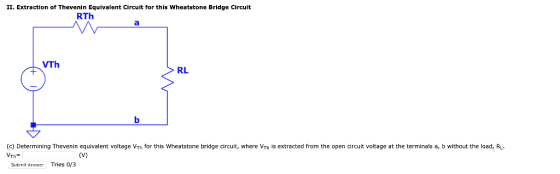
II. Extraction of Thevenin Equivalent Circuit for this Wheatstone Bridge Circuit RTh VTh RL (c) Determining Thevenin equivalent voltage VTh for this Wheatstone bridge circuit, where VTh is extracted from the open circuit voltage at the terminals a, b without the load, RL Th = Submit Answer Tries o/3
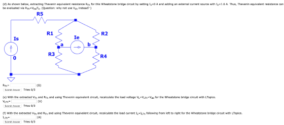
(d) As shown below, extracting Thevenin equivalent resistance Rh for this Wheatstone bridge circuit by setting Is be evaluated via RTh-Vba/le- (Question: why not use Vab instead?) A and adding an external current source with Ic-1.6 A. Thus, Thevenin equivalent resistance can R5 R1 R2 Is Ie R3 0 R4 (S2) Submit Answer Tries 0/3 (e) With the extracted VTh and RTh and using Thevenin equivalent circuit, recalculate the load voltage VL VLTh Vab for the Wheatstone bridge circuit with LTspice. LTh Subrnit Arisw Tries 0/3 (f) with the extracted Vm and Rn and using Thevenin equivalent circuit, recalculate the load current IL LTh following from left to right for the wheatstone bridge circuit with LTspice Submit Answer Tries 0/3
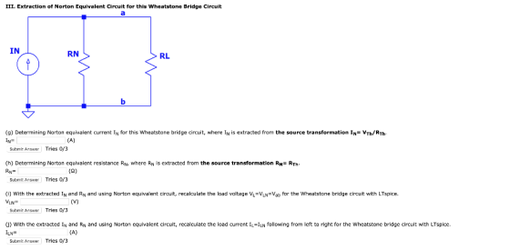
III. Extraction of Norton Equivalent Circuit for this Wheatstone Bridge Circuit IN RN RL (g) Determining Norton equivalent current IN for this wheatstone bridge circuit, where IN 1s extracted from the source transformation IN= VTh/Rh IN- Suhmit Answer Tries 0/3 (h) Determining Norton equivalent resistance RN, where R is extracted from the source transformation RN RTh Submit Answer| Tries 0/3 (i) With the extracted IN and RN and using Norton equivalent circuit, recalculate the load voltage VL-VLN-Vab for the wheatstone bridge circuit with LTspice. VLN Submit Answer Tries 0/3 (j) with the extracted IN and RN and using Norton equivalent circuit, recalculate the load current IL=ILN following from left to right for the wheatstone bridge circuit with LTspice. Submit Answer Tries 0/3
Homework Answers
Add Answer to:
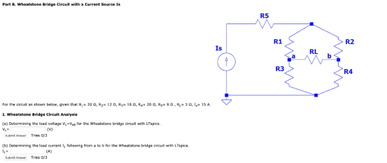
Part B. Wheatstone Bridge Circuit with a Current Source Is R5 R1 R2 Is RL R3 R4 For the circuit a...
Mini-Prj 2. Extraction of Thevenin and Norton Equivalent Circuits by LTspice Part A. Wheatstone B...
 Mini-Prj 2. Extraction of Thevenin and Norton Equivalent Circuits by LTspice Part A. Wheatstone Bridge Circuit with a Voltage Source Vs R5 R1 R2 Vs RL R3 R4 For the circuit as shown below, given that R1= 9 Ω, R2= 17 Ω, R3= 9 Ω' R,-18 Ω, R5= 19 Ω , RL= 2 Ω ,V,-74 V I. Wheatstone Bridge Circuit Analysis (a) Determining the load voltage Vi-Vab for the Wheatstone bridge circuit with LTspice Submit Answer Tries 0/3 (b) Determining...
Mini-Prj 2. Extraction of Thevenin and Norton Equivalent Circuits by LTspice Part B. Wheatstone B...
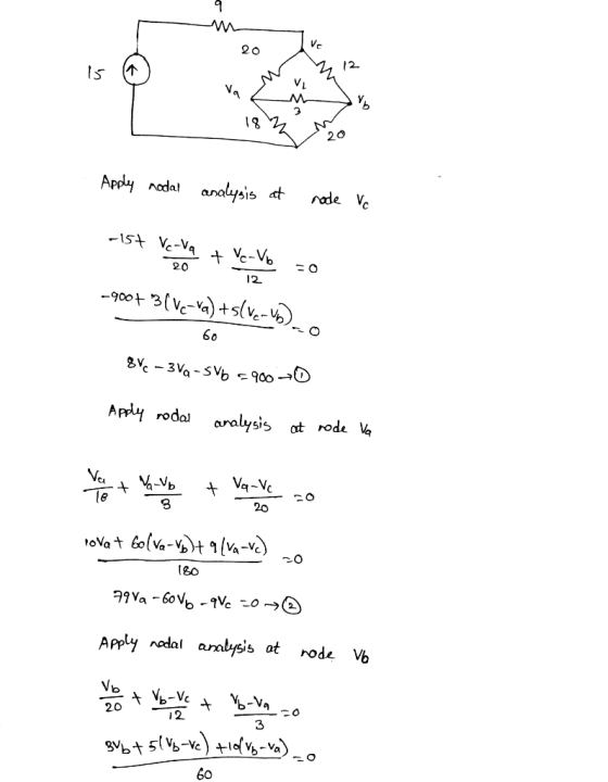
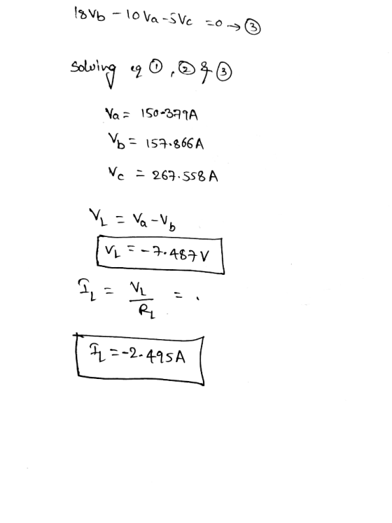
 Mini-Prj 2. Extraction of Thevenin and Norton Equivalent Circuits by LTspice Part B. Wheatstone Bridge Circuit with a Current Source Is R5 R1 R2 Is RL R3 R4 For the circuit as shown below, given that R1-22 Ω, R2-15 Ω, R3-28 Ω, R4-9 Ω, R5-29 Ω , R.-16 Ω, 1,-6 A. I. Wheatstone Bridge Circuit Analysis (a) Determining the load voltage VL-Vab for the Wheatstone bridge circuit with LTspice. Submit Answer Tries 0/4 (b) Determining the load current IL following...
Part A. Wheatstone Bridge Circuit with a Voltage Source Vs R5 R1 R2 Vs RL R3 R4 For the circuit a...
 Part A. Wheatstone Bridge Circuit with a Voltage Source Vs R5 R1 R2 Vs RL R3 R4 For the circuit as shown below, given that R1: 23 Ω, R2° 13 O, R,-230, R4% 3 Ω. RS: 28 Ω , RL: 13 Ω ,Vs-90 . I. Wheatstone Bridge Circuit Analysis (a) Determining the load voltage VL-Vab for the Wheatstone bridge circuit with LTspice 1 Submit Answer Tries 0/3 (b) Determining the load current I following from a to b for the...
Please show all work Question 3 (3 points) R1 RL R2 R3 The circuit above has...
 Please show all work
Question 3 (3 points) R1 RL R2 R3 The circuit above has the following values: V 55 V. R1-120 Ω. R2-910 Ω and R3 = 100 Ω. Determine the Thevenin voltage and resistance (c) VTH-55.00 V and RTH " 206.02 Ω VTH = 48.59 V and RTH = 206.02 Ω VTH 55.00 V and RTH 106.02 0 VTH 48.56 V and RTH 106,022
Please show all work
Question 3 (3 points) R1 RL R2 R3 The circuit above has the following values: V 55 V. R1-120 Ω. R2-910 Ω and R3 = 100 Ω. Determine the Thevenin voltage and resistance (c) VTH-55.00 V and RTH " 206.02 Ω VTH = 48.59 V and RTH = 206.02 Ω VTH 55.00 V and RTH 106.02 0 VTH 48.56 V and RTH 106,022
This circuit is a Wheatstone Bridge. It is used for numerous scientific and engineering applications. Here,...
 This circuit is a Wheatstone Bridge. It is used for numerous
scientific and engineering applications. Here, R1 = 20 kΩ, R2 = 10
kΩ, R3 = 5 kΩ, and R4 = 10 kΩ. ε = 5 V.
a) Determine the Thevenin equivalent resistance RTH between
points A and B. (Hint: when we remove the power supply and short
the circuit, the wire connecting the “top” and “bottom” of the
bridge can then be drawn to go right down the center...
This circuit is a Wheatstone Bridge. It is used for numerous
scientific and engineering applications. Here, R1 = 20 kΩ, R2 = 10
kΩ, R3 = 5 kΩ, and R4 = 10 kΩ. ε = 5 V.
a) Determine the Thevenin equivalent resistance RTH between
points A and B. (Hint: when we remove the power supply and short
the circuit, the wire connecting the “top” and “bottom” of the
bridge can then be drawn to go right down the center...
In the circuit below, R1-42 Ω R2-82 Ω R3-137 Ω R4 43 Ω R5-219 Ω and...
 In the circuit below, R1-42 Ω R2-82 Ω R3-137 Ω R4 43 Ω R5-219 Ω and the voltage supplied by the power supply is V1 R1 R2 R5 R3 R4 What is the current flowing through resistor R1? Submit Answer Tries 0/20 What is power dissipated by resistor R1? Submit Answer Tries 0/20
it's circuit tion 12 ed out of 2 lag R1 R3 R5 2 R2 R4 For...
 it's circuit
tion 12 ed out of 2 lag R1 R3 R5 2 R2 R4 For the bridge circuit shown, what is the value of the voltage V2 in volts? (Hint Use Thevenin equivalents to solve this problem more easily) Use
it's circuit
tion 12 ed out of 2 lag R1 R3 R5 2 R2 R4 For the bridge circuit shown, what is the value of the voltage V2 in volts? (Hint Use Thevenin equivalents to solve this problem more easily) Use
For the circuit of Figure 1, choose values for resistors R1, R2, and R3
 C.la For the circuit of Figure 1, choose values for resistors R1, R2, and R3(all resistances must be greater than one Kilo ohm). Given that the voltage source Vs1 = 8V and Vs2 = 10V determine the output voltage Vout. C.1b For the same resistor values Ri, R2, and Rs you chose in part C.la Given that the voltage source Vsi = 8V and Vs2 = 10V, use Figure 2(a) to determine the output voltage Vout/ and Figure 2(b) to determine the output voltage Vout2. Discussion:...
R1 C1 HH The V1 R2 11 R3 circuit shown is a simplified representation of a...
 R1 C1 HH The V1 R2 11 R3 circuit shown is a simplified representation of a small signal transistor amplifier circuit. The AC input voltage is V1, with angular frequency w. The current through R2, is It. The dependent current source, 11, has value 100 IV. Let R1 = 500, and R2 = 1000. The load resistor, R3 has a value that is selectable by a design engineer. Let C1 = 10 pF, and L1 = 1 uH. (For reference,...
 Mini-Prj 2. Extraction of Thevenin and Norton Equivalent Circuits by LTspice Part A. Wheatstone Bridge Circuit with a Voltage Source Vs R5 R1 R2 Vs RL R3 R4 For the circuit as shown below, given that R1= 9 Ω, R2= 17 Ω, R3= 9 Ω' R,-18 Ω, R5= 19 Ω , RL= 2 Ω ,V,-74 V I. Wheatstone Bridge Circuit Analysis (a) Determining the load voltage Vi-Vab for the Wheatstone bridge circuit with LTspice Submit Answer Tries 0/3 (b) Determining...
 Mini-Prj 2. Extraction of Thevenin and Norton Equivalent Circuits by LTspice Part A. Wheatstone Bridge Circuit with a Voltage Source Vs R5 R1 R2 Vs RL R3 R4 For the circuit as shown below, given that R1= 9 Ω, R2= 17 Ω, R3= 9 Ω' R,-18 Ω, R5= 19 Ω , RL= 2 Ω ,V,-74 V I. Wheatstone Bridge Circuit Analysis (a) Determining the load voltage Vi-Vab for the Wheatstone bridge circuit with LTspice Submit Answer Tries 0/3 (b) Determining...
 Mini-Prj 2. Extraction of Thevenin and Norton Equivalent Circuits by LTspice Part B. Wheatstone Bridge Circuit with a Current Source Is R5 R1 R2 Is RL R3 R4 For the circuit as shown below, given that R1-22 Ω, R2-15 Ω, R3-28 Ω, R4-9 Ω, R5-29 Ω , R.-16 Ω, 1,-6 A. I. Wheatstone Bridge Circuit Analysis (a) Determining the load voltage VL-Vab for the Wheatstone bridge circuit with LTspice. Submit Answer Tries 0/4 (b) Determining the load current IL following...
 Part A. Wheatstone Bridge Circuit with a Voltage Source Vs R5 R1 R2 Vs RL R3 R4 For the circuit as shown below, given that R1: 23 Ω, R2° 13 O, R,-230, R4% 3 Ω. RS: 28 Ω , RL: 13 Ω ,Vs-90 . I. Wheatstone Bridge Circuit Analysis (a) Determining the load voltage VL-Vab for the Wheatstone bridge circuit with LTspice 1 Submit Answer Tries 0/3 (b) Determining the load current I following from a to b for the...
 Please show all work
Question 3 (3 points) R1 RL R2 R3 The circuit above has the following values: V 55 V. R1-120 Ω. R2-910 Ω and R3 = 100 Ω. Determine the Thevenin voltage and resistance (c) VTH-55.00 V and RTH " 206.02 Ω VTH = 48.59 V and RTH = 206.02 Ω VTH 55.00 V and RTH 106.02 0 VTH 48.56 V and RTH 106,022
Please show all work
Question 3 (3 points) R1 RL R2 R3 The circuit above has the following values: V 55 V. R1-120 Ω. R2-910 Ω and R3 = 100 Ω. Determine the Thevenin voltage and resistance (c) VTH-55.00 V and RTH " 206.02 Ω VTH = 48.59 V and RTH = 206.02 Ω VTH 55.00 V and RTH 106.02 0 VTH 48.56 V and RTH 106,022
 This circuit is a Wheatstone Bridge. It is used for numerous
scientific and engineering applications. Here, R1 = 20 kΩ, R2 = 10
kΩ, R3 = 5 kΩ, and R4 = 10 kΩ. ε = 5 V.
a) Determine the Thevenin equivalent resistance RTH between
points A and B. (Hint: when we remove the power supply and short
the circuit, the wire connecting the “top” and “bottom” of the
bridge can then be drawn to go right down the center...
This circuit is a Wheatstone Bridge. It is used for numerous
scientific and engineering applications. Here, R1 = 20 kΩ, R2 = 10
kΩ, R3 = 5 kΩ, and R4 = 10 kΩ. ε = 5 V.
a) Determine the Thevenin equivalent resistance RTH between
points A and B. (Hint: when we remove the power supply and short
the circuit, the wire connecting the “top” and “bottom” of the
bridge can then be drawn to go right down the center...
 In the circuit below, R1-42 Ω R2-82 Ω R3-137 Ω R4 43 Ω R5-219 Ω and the voltage supplied by the power supply is V1 R1 R2 R5 R3 R4 What is the current flowing through resistor R1? Submit Answer Tries 0/20 What is power dissipated by resistor R1? Submit Answer Tries 0/20
 it's circuit
tion 12 ed out of 2 lag R1 R3 R5 2 R2 R4 For the bridge circuit shown, what is the value of the voltage V2 in volts? (Hint Use Thevenin equivalents to solve this problem more easily) Use
it's circuit
tion 12 ed out of 2 lag R1 R3 R5 2 R2 R4 For the bridge circuit shown, what is the value of the voltage V2 in volts? (Hint Use Thevenin equivalents to solve this problem more easily) Use
 C.la For the circuit of Figure 1, choose values for resistors R1, R2, and R3(all resistances must be greater than one Kilo ohm). Given that the voltage source Vs1 = 8V and Vs2 = 10V determine the output voltage Vout. C.1b For the same resistor values Ri, R2, and Rs you chose in part C.la Given that the voltage source Vsi = 8V and Vs2 = 10V, use Figure 2(a) to determine the output voltage Vout/ and Figure 2(b) to determine the output voltage Vout2. Discussion:...
 R1 C1 HH The V1 R2 11 R3 circuit shown is a simplified representation of a small signal transistor amplifier circuit. The AC input voltage is V1, with angular frequency w. The current through R2, is It. The dependent current source, 11, has value 100 IV. Let R1 = 500, and R2 = 1000. The load resistor, R3 has a value that is selectable by a design engineer. Let C1 = 10 pF, and L1 = 1 uH. (For reference,...
Most questions answered within 3 hours.
-
4. The excitation of a 414 V, 3-phase, delta-connected
synchronous motor is such that that the...
asked 14 minutes ago -
3. (20 pts) In the Carnot engine (refer to the figure in
question 2), an ideal...
asked 21 minutes ago -
A contestant is facing 10 closed doors. Behind one of these
doors there is a prize....
asked 23 minutes ago -
Showing appropriate work and equations, what is the yield to
maturity on a share of Six...
asked 38 minutes ago -
what would be the best entry mode in shipping from the U.S to Spain
by boat...
asked 43 minutes ago -
Under certain conditions, the substance ammonium
nitrate can be broken down to form dinitrogen
monoxide and...
asked 44 minutes ago -
1. A boy stands on one end of a boat, and then walks to the
other...
asked 54 minutes ago -
Casey is on trial under criminal allegations that she engaged in
fraudulent behavior at the company...
asked 59 minutes ago -
Surplus Styles is a manufacturer of hair care products,
including shampoos, conditioners, and hair gels. The...
asked 58 minutes ago -
Using an income-expenditure diagram, use the infinite line and
double-drop line tools to show the economy...
asked 1 hour ago -
Which expression computes a pseudorandom integer between -10 and
10 using rand()
from cstdlib?
A. (rand(...
asked 1 hour ago -
Roybus, Inc., a manufacturer of flash memory, just reported that
its main production facility in Taiwan...
asked 1 hour ago