


II. Extraction of Thevenin Equivalent Circuit for this Wheatstone Bridge Circuit RTh VTh RL (c) Determining Thevenin equivalent voltage VTh for this Wheatstone bridge circuit, where VTh is extracted from the open circuit voltage at the terminals a, b without the load, RL Submit Answer Tries o/3 (d) As shown below, extracting Thevenin equivalent resistance RTh for this Wheatstone bridge circuit by setting Vs-0 V and adding an external current source with Le-1.2 A. Thus, Thevenin equivalent resistance can be evaluated via RThV (Question: why not use Vab instead?)
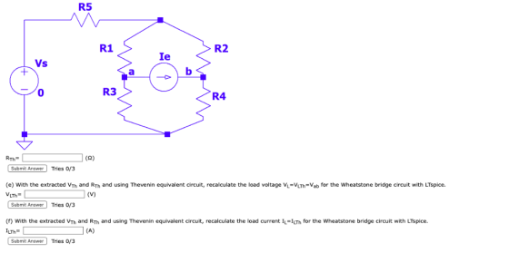
R5 R1 R2 Ie Vs 0 R3 R4 (S2) Submit Answer Tries 0/3 (e) With the extracted VTh and RTh and using Thevenin equivalent circuit, recalculate the load voltage Vu-VLTh-Vab for the Wheatstone bridge circuit with LTspice VLTh Submit Answer Tries 0/3 ) With the extracted VTh and RTh and using Thevenin equivalent circuit, recalculate the load current IL-ILTh for the Wheatstone bridge circuit with LTspice. ILM" Submit Answer Tries 0/3
III. Extraction of Norton Equivalent Circuit for this Wheatstone Bridge Circuit IN RN RL (g) Determining Norton equivalent current IN for this Wheatstone bridge circuit, where IN is extracted from the source transformation IN VTh/RTh IN- Submit Answer Tries 0/3 (h) Determining Norton equivalent resistance RN, where RN is extracted from the source transformation RN-RTh RN Submit Answer Tries 0/3 (i) with the extracted IN and RN and using Norton equivalent circuit, recalculate the load voltage VL-VLN=Vab for the Wheatstone bridge circuit with LTSpice. VLN Submit Answer Tries 0/3 ) With the extracted IN and RN and using Norton equivalent circuit, recalculate the load current IL ILN for the Wheatstone bridge circuit with LTspice. Submit Answer Tries 0/3 ILN
Mini-Prj 2. Extraction of Thevenin and Norton Equivalent Circuits by LTspice Part B. Wheatstone Bridge Circuit with a Current Source Is R5 R1 R2 Is RL R3 R4 For the circuit as shown below, given that R1-22 Ω, R2-15 Ω, R3-28 Ω, R4-9 Ω, R5-29 Ω , R.-16 Ω, 1,-6 A. I. Wheatstone Bridge Circuit Analysis (a) Determining the load voltage VL-Vab for the Wheatstone bridge circuit with LTspice. Submit Answer Tries 0/4 (b) Determining the load current IL following from a to b for the Wheatstone bridge circuit with LTspice Submit Answer Tries 0/4
II. Extraction of Thevenin Equivalent Circuit for this Wheatstone Bridge Circuit RTh VTh RL (c) Determining Thevenin equivalent voltage VTh for this Wheatstone bridge circuit, where VTh is extracted from the open circuit voltage at the terminals a, b without the load, RL Submit Answer Tries 0/3 d) As shown below, extracting Thevenin equivalent resistance RTh or this wheatstone bridge circuit by setting 1s=0 A and adding an external current source with e=1.2 A. Thus, Thevenin equivalent resistan can be evaluated via RTh Va/e (Question: why not use Vab instead?)
R5 R1 R2 Is Ie R3 R4 0 Submit Answer Tries 0/3 (e) With the extracted VTh and RTh and using Thevenin equivalent circuit, recalculate the load voltage V VLTh-Vab for the Wheatstone bridge circuit with LTspice. Submit Answer Tries 0/3 (f) With the extracted VTh and RTh and using Thevenin equivalent circuit, recalculate the load current ILILTh following from left to right for the Wheatstone bridge circuit with LTspice ILTh Submit Answer Tries 0/3
III. Extraction of Norton Equivalent Circuit for this Wheatstone Bridge Circuit IN RN RL (g) Determining Norton equivalent current IN for this wheatstone bridge circuit, where IN įs extracted from the source transformation 1N= Vrh/RT- 1 (A) Submit Answer Tries 0/3 (h) Determining Norton equivalent resistance RN, where RN is extracted from the source transformation RN RN- RTh Submit Answer Tries 0/3 ) With the extracted IN and RN and using Norton equivalent circuit, recalculate the load voltage VL-VLN-Vab for the Wheatstone bridge circuit with LTspice VUN Submit Answer Tries 0/3 ) With the extracted IN and Rv and using Norton equivalent circuit, recalculate the load current IL ILN following from left to right for the Wheatstone bridge circuit with LTspice. ILN Submit Answer Tries 0/3
Homework Answers
I. I have simulated the given wheat stone bridge using LTspice and results are shown below
![LTspice XVII Draft1 Eile View Plot Settings Simulation Iools Window Help Egi Adi刍ㄧㄥ女叩之 3 D-纱屮り EmE] Aa op Draftt R5 19 R2 17](http://img.homeworklib.com/images/128d3040-46a5-4978-a4cc-dd0216fbbda5.png?x-oss-process=image/resize,w_560)
![LTspice XVII - Draft Eile View Plot Settings Simulation Iools Window Help ] Τ 茅49 Q Q皋賒ig E 義더 R龉生刍 / 回ぐ 3 D-epY Of E Aa.op](http://img.homeworklib.com/images/51d6248c-3e55-4a6c-bd98-2b82837f7b11.png?x-oss-process=image/resize,w_560)
Waveforms for V(a) and V(b) can be shown on the same graph,but I have shown them on different graphs in this first step.
From simulations we have, V(a)=14.358 V and V(b)=14.411 V

Therefore, V(ab) = VL= -0.052 V.

From simulation graph .Load current I(RL)=26.688 mA
Therefore, I(RL)=IL=0.0268 A
2. Now finding Vth by removing RL , we have

Va(black line in graph)=14.24 V, Vb(Pink line in graph)=14.64 V
Therefore , Vth= Va - Vb = 14.24 - 14.64 = -0.4 V
Therefore Vth= -0.4 V
For Rth, current source=1.2 A is applied between a and b as shown below
 Therefore
Vba=Vb - Va = 25 - 9 = 16 V ,
Current source (I1)=1.2 A
Therefore
Vba=Vb - Va = 25 - 9 = 16 V ,
Current source (I1)=1.2 A
Rth=Vba/I1 = 16/1.2 = 13.33 ohm
Therefore , Rth=13.33 ohm
Therefore Thevenin equivalent circuit we have ,
 Vb=0 V(gnd),
Va(black line)= -52.2 mV= -0.052 V , therefore
Va - Vb=
Vab=VLth= -0.052
V ,Hence same as above calculated.
Vb=0 V(gnd),
Va(black line)= -52.2 mV= -0.052 V , therefore
Va - Vb=
Vab=VLth= -0.052
V ,Hence same as above calculated.
IL= 26.2 mA(pink line in graph)
Hence ILth= 0.0262 A (nearly same as above calculated)
Now Norton equivalent circuit we have , In=Vth/Rth= -0.4/13.33 = -0.03 A , Rn=Rth= 13.33 ohm

Therefore from graph we have VLn=Va - Vb= -52.2mV -0 = -52.2 mV , therefore VLn= - 0.052 V
ILn=0.0262 A
As per HomeworkLib policy I have solved first question as you have posted multiple question. feel free to ask if you have any query.Thank you
Add Answer to:
Mini-Prj 2. Extraction of Thevenin and Norton Equivalent Circuits by LTspice Part A. Wheatstone B...
Mini-Prj 2. Extraction of Thevenin and Norton Equivalent Circuits by LTspice Part A. Wheatstone B...
 Mini-Prj 2. Extraction of Thevenin and Norton Equivalent Circuits by LTspice Part A. Wheatstone Bridge Circuit with a Voltage Source Vs R5 R1 R2 Vs RL R3 R4 For the circuit as shown below, given that R1= 9 Ω, R2= 17 Ω, R3= 9 Ω' R,-18 Ω, R5= 19 Ω , RL= 2 Ω ,V,-74 V I. Wheatstone Bridge Circuit Analysis (a) Determining the load voltage Vi-Vab for the Wheatstone bridge circuit with LTspice Submit Answer Tries 0/3 (b) Determining...
Mini-Prj 2. Extraction of Thevenin and Norton Equivalent Circuits by LTspice Part B. Wheatstone B...
 Mini-Prj 2. Extraction of Thevenin and Norton Equivalent Circuits by LTspice Part B. Wheatstone Bridge Circuit with a Current Source Is R5 R1 R2 Is RL R3 R4 For the circuit as shown below, given that R1-22 Ω, R2-15 Ω, R3-28 Ω, R4-9 Ω, R5-29 Ω , R.-16 Ω, 1,-6 A. I. Wheatstone Bridge Circuit Analysis (a) Determining the load voltage VL-Vab for the Wheatstone bridge circuit with LTspice. Submit Answer Tries 0/4 (b) Determining the load current IL following...
Part B. Wheatstone Bridge Circuit with a Current Source Is R5 R1 R2 Is RL R3 R4 For the circuit a...
 Part B. Wheatstone Bridge Circuit with a Current Source Is R5 R1 R2 Is RL R3 R4 For the circuit as shown below, given that R1-20 Ω,R2= 12 Ω, R3-18 Ω, R4= 20 Ω, R5= 9 Ω , R.-3 ΩΊ,-15 A. I. Wheatstone Bridge Circuit Analysis (a) Determining the load voltage VL-Vab for the Wheatstone bridge circuit with LTspice. Subrnit Answer Tries 0/3 (b) Determining the load current I following from a to b for the Wheatstone bridge circuit with...
Part A. Wheatstone Bridge Circuit with a Voltage Source Vs R5 R1 R2 Vs RL R3 R4 For the circuit a...
 Part A. Wheatstone Bridge Circuit with a Voltage Source Vs R5 R1 R2 Vs RL R3 R4 For the circuit as shown below, given that R1: 23 Ω, R2° 13 O, R,-230, R4% 3 Ω. RS: 28 Ω , RL: 13 Ω ,Vs-90 . I. Wheatstone Bridge Circuit Analysis (a) Determining the load voltage VL-Vab for the Wheatstone bridge circuit with LTspice 1 Submit Answer Tries 0/3 (b) Determining the load current I following from a to b for the...
V1 = 20 V2 = 25 EXPERIMENT NO. 6 Thevenin & Norton Theorem Introduction Any linear...
 V1 = 20 V2 = 25
EXPERIMENT NO. 6 Thevenin & Norton Theorem Introduction Any linear network having a number of voltage, current sources and resistors can be replaced by a simple equivalent circuit consisting of a single voltage source in series with a resistance, where the value of the voltage source is equalto the open circuit voltage and the resistance is the equivalent resistance measuredbetweenthe open circuit terminals with all independent deactivated Objective To verify Thevenin's and Norton's theoremusing...
V1 = 20 V2 = 25
EXPERIMENT NO. 6 Thevenin & Norton Theorem Introduction Any linear network having a number of voltage, current sources and resistors can be replaced by a simple equivalent circuit consisting of a single voltage source in series with a resistance, where the value of the voltage source is equalto the open circuit voltage and the resistance is the equivalent resistance measuredbetweenthe open circuit terminals with all independent deactivated Objective To verify Thevenin's and Norton's theoremusing...
Find the Thevenin and Norton equivalent circuit at terminals a-b for the circuit shown below, where...
 Find the Thevenin and Norton equivalent circuit at terminals
a-b for the circuit shown below, where R
= 12 Ω. Please report your answer so the magnitude is positive and
all angles are in the range of negative 180 degrees to positive 180
degrees.
Find the Thevenin and Norton equivalent circuit at terminals a-b for the circuit shown below, where R = 12 n. Please report your answer so the magnitude is positive and all angles are in the range...
Find the Thevenin and Norton equivalent circuit at terminals
a-b for the circuit shown below, where R
= 12 Ω. Please report your answer so the magnitude is positive and
all angles are in the range of negative 180 degrees to positive 180
degrees.
Find the Thevenin and Norton equivalent circuit at terminals a-b for the circuit shown below, where R = 12 n. Please report your answer so the magnitude is positive and all angles are in the range...
Find the Thevenin and Norton equivalent circuit at terminals a-b for the circuit shown below, where...
 Find the Thevenin and Norton equivalent circuit at
terminals a-b for the circuit shown below, where R =10 ohms. Please
report your answer so the magnitude is positive and all angles are
in the range of negative 180 degrees to positive 180 degrees.
Find the Thevenin and Norton equivalent circuit at terminals a-b for the circuit shown below, where R = 10 . Please report your answer so the magnitude is positive and all angles are in the range of...
Find the Thevenin and Norton equivalent circuit at
terminals a-b for the circuit shown below, where R =10 ohms. Please
report your answer so the magnitude is positive and all angles are
in the range of negative 180 degrees to positive 180 degrees.
Find the Thevenin and Norton equivalent circuit at terminals a-b for the circuit shown below, where R = 10 . Please report your answer so the magnitude is positive and all angles are in the range of...
Find the Thevenin and Norton equivalent circuit at terminals a-b for the circuit shown below, where...
 Find the Thevenin and Norton equivalent circuit at terminals a-b for the circuit shown below, where R = 13 12. Please report your answer so the magnitude is positive and all angles are in the range of negative 180 degrees to positive 180 degrees. j42 R mo юа -j2 Ω 2/0° A -ob Zn = = Zth IN = 1) D A 1) v Vth =
A. Calculate Vout for both circuits by hand and include your calculations in your Pre-Lab B. Build the circuits in LTSpice and attach a 10K ohm termination resistor across Vout for both the Thevenin...
 A. Calculate Vout for both circuits by hand and include your
calculations in your Pre-Lab
B. Build the circuits in LTSpice and attach a 10K ohm
termination resistor across Vout for
both the Thevenin and Norton Source circuits and simulate to
find the output voltages.
C. What is the formula for Vout as a function of Vsource,
Isource, Rload, Rs?
D. Calculate Vout by hand when there is no load resistance
(Rload = infinity) and again
with Rload = 5K....
A. Calculate Vout for both circuits by hand and include your
calculations in your Pre-Lab
B. Build the circuits in LTSpice and attach a 10K ohm
termination resistor across Vout for
both the Thevenin and Norton Source circuits and simulate to
find the output voltages.
C. What is the formula for Vout as a function of Vsource,
Isource, Rload, Rs?
D. Calculate Vout by hand when there is no load resistance
(Rload = infinity) and again
with Rload = 5K....
Find the Thevenin and Norton equivalent circuit at terminals a-b for the circuit shown below, where...
 Find the Thevenin and Norton equivalent circuit at terminals a-b for the circuit shown below, where R = 10 . Please report your answer so the magnitude is positive and all angles are in the range of negative 180 degrees to positive 180 degrees. 1422 R -j2 22 2/0° A ob 1) ZN = Zth = IN Vth A 1) v
 Mini-Prj 2. Extraction of Thevenin and Norton Equivalent Circuits by LTspice Part A. Wheatstone Bridge Circuit with a Voltage Source Vs R5 R1 R2 Vs RL R3 R4 For the circuit as shown below, given that R1= 9 Ω, R2= 17 Ω, R3= 9 Ω' R,-18 Ω, R5= 19 Ω , RL= 2 Ω ,V,-74 V I. Wheatstone Bridge Circuit Analysis (a) Determining the load voltage Vi-Vab for the Wheatstone bridge circuit with LTspice Submit Answer Tries 0/3 (b) Determining...
 Mini-Prj 2. Extraction of Thevenin and Norton Equivalent Circuits by LTspice Part B. Wheatstone Bridge Circuit with a Current Source Is R5 R1 R2 Is RL R3 R4 For the circuit as shown below, given that R1-22 Ω, R2-15 Ω, R3-28 Ω, R4-9 Ω, R5-29 Ω , R.-16 Ω, 1,-6 A. I. Wheatstone Bridge Circuit Analysis (a) Determining the load voltage VL-Vab for the Wheatstone bridge circuit with LTspice. Submit Answer Tries 0/4 (b) Determining the load current IL following...
 Part B. Wheatstone Bridge Circuit with a Current Source Is R5 R1 R2 Is RL R3 R4 For the circuit as shown below, given that R1-20 Ω,R2= 12 Ω, R3-18 Ω, R4= 20 Ω, R5= 9 Ω , R.-3 ΩΊ,-15 A. I. Wheatstone Bridge Circuit Analysis (a) Determining the load voltage VL-Vab for the Wheatstone bridge circuit with LTspice. Subrnit Answer Tries 0/3 (b) Determining the load current I following from a to b for the Wheatstone bridge circuit with...
 Part A. Wheatstone Bridge Circuit with a Voltage Source Vs R5 R1 R2 Vs RL R3 R4 For the circuit as shown below, given that R1: 23 Ω, R2° 13 O, R,-230, R4% 3 Ω. RS: 28 Ω , RL: 13 Ω ,Vs-90 . I. Wheatstone Bridge Circuit Analysis (a) Determining the load voltage VL-Vab for the Wheatstone bridge circuit with LTspice 1 Submit Answer Tries 0/3 (b) Determining the load current I following from a to b for the...
 V1 = 20 V2 = 25
EXPERIMENT NO. 6 Thevenin & Norton Theorem Introduction Any linear network having a number of voltage, current sources and resistors can be replaced by a simple equivalent circuit consisting of a single voltage source in series with a resistance, where the value of the voltage source is equalto the open circuit voltage and the resistance is the equivalent resistance measuredbetweenthe open circuit terminals with all independent deactivated Objective To verify Thevenin's and Norton's theoremusing...
V1 = 20 V2 = 25
EXPERIMENT NO. 6 Thevenin & Norton Theorem Introduction Any linear network having a number of voltage, current sources and resistors can be replaced by a simple equivalent circuit consisting of a single voltage source in series with a resistance, where the value of the voltage source is equalto the open circuit voltage and the resistance is the equivalent resistance measuredbetweenthe open circuit terminals with all independent deactivated Objective To verify Thevenin's and Norton's theoremusing...
 Find the Thevenin and Norton equivalent circuit at terminals
a-b for the circuit shown below, where R
= 12 Ω. Please report your answer so the magnitude is positive and
all angles are in the range of negative 180 degrees to positive 180
degrees.
Find the Thevenin and Norton equivalent circuit at terminals a-b for the circuit shown below, where R = 12 n. Please report your answer so the magnitude is positive and all angles are in the range...
Find the Thevenin and Norton equivalent circuit at terminals
a-b for the circuit shown below, where R
= 12 Ω. Please report your answer so the magnitude is positive and
all angles are in the range of negative 180 degrees to positive 180
degrees.
Find the Thevenin and Norton equivalent circuit at terminals a-b for the circuit shown below, where R = 12 n. Please report your answer so the magnitude is positive and all angles are in the range...
 Find the Thevenin and Norton equivalent circuit at
terminals a-b for the circuit shown below, where R =10 ohms. Please
report your answer so the magnitude is positive and all angles are
in the range of negative 180 degrees to positive 180 degrees.
Find the Thevenin and Norton equivalent circuit at terminals a-b for the circuit shown below, where R = 10 . Please report your answer so the magnitude is positive and all angles are in the range of...
Find the Thevenin and Norton equivalent circuit at
terminals a-b for the circuit shown below, where R =10 ohms. Please
report your answer so the magnitude is positive and all angles are
in the range of negative 180 degrees to positive 180 degrees.
Find the Thevenin and Norton equivalent circuit at terminals a-b for the circuit shown below, where R = 10 . Please report your answer so the magnitude is positive and all angles are in the range of...
 Find the Thevenin and Norton equivalent circuit at terminals a-b for the circuit shown below, where R = 13 12. Please report your answer so the magnitude is positive and all angles are in the range of negative 180 degrees to positive 180 degrees. j42 R mo юа -j2 Ω 2/0° A -ob Zn = = Zth IN = 1) D A 1) v Vth =
 A. Calculate Vout for both circuits by hand and include your
calculations in your Pre-Lab
B. Build the circuits in LTSpice and attach a 10K ohm
termination resistor across Vout for
both the Thevenin and Norton Source circuits and simulate to
find the output voltages.
C. What is the formula for Vout as a function of Vsource,
Isource, Rload, Rs?
D. Calculate Vout by hand when there is no load resistance
(Rload = infinity) and again
with Rload = 5K....
A. Calculate Vout for both circuits by hand and include your
calculations in your Pre-Lab
B. Build the circuits in LTSpice and attach a 10K ohm
termination resistor across Vout for
both the Thevenin and Norton Source circuits and simulate to
find the output voltages.
C. What is the formula for Vout as a function of Vsource,
Isource, Rload, Rs?
D. Calculate Vout by hand when there is no load resistance
(Rload = infinity) and again
with Rload = 5K....
 Find the Thevenin and Norton equivalent circuit at terminals a-b for the circuit shown below, where R = 10 . Please report your answer so the magnitude is positive and all angles are in the range of negative 180 degrees to positive 180 degrees. 1422 R -j2 22 2/0° A ob 1) ZN = Zth = IN Vth A 1) v
Most questions answered within 3 hours.
-
38%
of adults say cashews are their favorite kind of nut. You
randomly select 12 adults...
asked 1 hour ago -
Notational Inc. is considering installing a new server. The
machine costs $100,000 and is expected to...
asked 59 minutes ago -
Given the information coding of DNA strand:
5'-TTT-TAC-GAA-GAG-TGA-3',
Write the corresponding DNA template and mRNA strand...
asked 1 hour ago -
2. Boris recently synthesized an explosive compound he named
Badenoughium. The molecular formula for Bdenoughium is...
asked 4 hours ago -
5. A car decelerate evenly from a velocity of 50mph until rest
in a distance of...
asked 5 hours ago -
IN HTML Programming
1. Write a script that inputs integers (one at a time) and
passes...
asked 5 hours ago -
A dentist uses a mirror to examine a tooth that is 0.75 cm in
front of...
asked 5 hours ago -
You set up a 100,000 line of credit for the business on 1/1/X8,
annual interest is...
asked 5 hours ago -
What is the measurement uncertainty of a pan balance? How did you
get that?
asked 5 hours ago -
Suppose four firms have market shares of 30%, 30%, 20% and 20%.
What is the Herfindahl-Hirschman...
asked 5 hours ago -
IBT Industrial Solutions produces forty units of rack and pinion
type steering gears during an eight...
asked 5 hours ago -
The Ksp for PbI2 is 9.8×10⁻⁹ . Will PbI2 precipitate if 2.5 mL
of 0.0025 M...
asked 5 hours ago