
Homework Answers


Add Answer to:
OUESTION 1 Anna is designing an audio amplifier for her headphones. She wants to calculate the real DC gain of the ampl...
3- OPERATIONAL-AMPLIFIER Nominating ampliar Voltage Show OW Difference ampliar Wate Date amplizier Close R Vout Voutin...
 3- OPERATIONAL-AMPLIFIER Nominating ampliar Voltage Show OW Difference ampliar Wate Date amplizier Close R Vout Voutin Vout = vin Buffer = Inverting amplifier Dout = (1 + .. Vout V out 1 V2 ERR Vour (, - v3) Differential Amplifier Non-Inverting amplifier 1- Refer to the op amp in Fig. If v; = 0.5 V, calculate: (a) the output voltage Vos (b) the current in the 10-k! resistor. 25k92 10k02 Oo + 6 2. A 741 op amp has an...
Laboratory 1: operation amplifier characteristics A. Objectives: 1. To study the basic characteri...
 thanks
Laboratory 1: operation amplifier characteristics A. Objectives: 1. To study the basic characteristics of an operational amplifier 2. To study the bias circuit of an operational amplifier B. Apparatus: 1. DC Power supply 2. Experimental board and corresponding components 3. Electronic calculator (prepared by students) 4. Digital camera (prepared by students for photo taking of the experimental results) 5. Laptop computer with the software PicoScope 6 and Microsoft Word installed. 6. PicoScope PC Oscilloscope and its accessories. 7. Multimeter...
thanks
Laboratory 1: operation amplifier characteristics A. Objectives: 1. To study the basic characteristics of an operational amplifier 2. To study the bias circuit of an operational amplifier B. Apparatus: 1. DC Power supply 2. Experimental board and corresponding components 3. Electronic calculator (prepared by students) 4. Digital camera (prepared by students for photo taking of the experimental results) 5. Laptop computer with the software PicoScope 6 and Microsoft Word installed. 6. PicoScope PC Oscilloscope and its accessories. 7. Multimeter...
QUESTION 1 Anna the Audiophile has asked for your help to build an amplifier and filter...
 QUESTION 1 Anna the Audiophile has asked for your help to build an amplifier and filter to take small signals from her hifi system and amplify them so that she can drive her new subwoofer. The hifi system produces AC signals at varying frequencies with 250mVrms maximum magnitude Her subwoofer requires the signals to be 20 Vrms maximum magnitude. The signals that Anna is interested in are below 200 Hz. She would like the filter to attenuate signals at frequencies...
Question 1 In the diagram of Superheterodne AM receiver shown below explain the function of each block. (a) 15 marks Antenna Speaker Audio and power amplifiers RF IF Mixer Detector Mi amplifier a...
 Question 1 In the diagram of Superheterodne AM receiver shown below explain the function of each block. (a) 15 marks Antenna Speaker Audio and power amplifiers RF IF Mixer Detector Mi amplifier amplifier AGC --_Local Gang tuned oscillator (b) For a 4-bit DAC, calculate the output voltage for an input code word 1010 if a [10 marks] logic 1 is 10V and a logic 0 is 0V, and R = RFI kΩ Total: 25 marks] Question 2 (a) Explain the...
Q1. You are given a 12 V DC power supply. You are expected to develop a voltage divider to achieve a voltage of no...
 Q1. You are given a 12 V DC power supply. You are expected to develop a voltage divider to achieve a voltage of nominal 5V value using a pair of resistors from the E 12 range, with the restrition that you are not expected to draw a current of more than 1 mA from the 12 V DC supply i. Develop a simple circuit showing the possible values for each resistor pair, and the range of the DC output possible...
(a) Design an inverting amplifier by choosing suitable resistor values for R1 and R2 to produce...
 (a) Design an inverting amplifier by choosing suitable resistor
values for R1 and R2 to produce a gain of 5 when both switches
Sw1 and Sw2 are open.
(b) Design the bias input circuit by choosing suitable resistors
R3 and R4 such that the voltage vb will be 0.5V if the
positive power supply of the op-amp is connected to a 5V battery.
Again both switches are open.
(c) Given Sw1 is open, the amplifier is turned on for
enough...
(a) Design an inverting amplifier by choosing suitable resistor
values for R1 and R2 to produce a gain of 5 when both switches
Sw1 and Sw2 are open.
(b) Design the bias input circuit by choosing suitable resistors
R3 and R4 such that the voltage vb will be 0.5V if the
positive power supply of the op-amp is connected to a 5V battery.
Again both switches are open.
(c) Given Sw1 is open, the amplifier is turned on for
enough...
Yes, this is one problem. Please solve ALL PARTS. Guaranteed thumbs up for the person who solves it. 3 1. Photodiode...
 Yes, this is one problem. Please solve ALL PARTS. Guaranteed
thumbs up for the person who solves it.
3 1. Photodiode amplifier circuit You are designinga CF photosensor circuit for a light detection and ranging LiDAR) system in autonomous vehicles. The circuit utilizes a transimpedance amplifier to convert low-level RF photodiode current signal to a usable voltage output. It consists of a photodiode, an amplifier, and feedback capacitor/resistor pair as shown in Figure 1. We will derive simple equations to...
Yes, this is one problem. Please solve ALL PARTS. Guaranteed
thumbs up for the person who solves it.
3 1. Photodiode amplifier circuit You are designinga CF photosensor circuit for a light detection and ranging LiDAR) system in autonomous vehicles. The circuit utilizes a transimpedance amplifier to convert low-level RF photodiode current signal to a usable voltage output. It consists of a photodiode, an amplifier, and feedback capacitor/resistor pair as shown in Figure 1. We will derive simple equations to...
The circuit shown in Figure Q4-1 includes an audio source and the equivalent circuit of a...
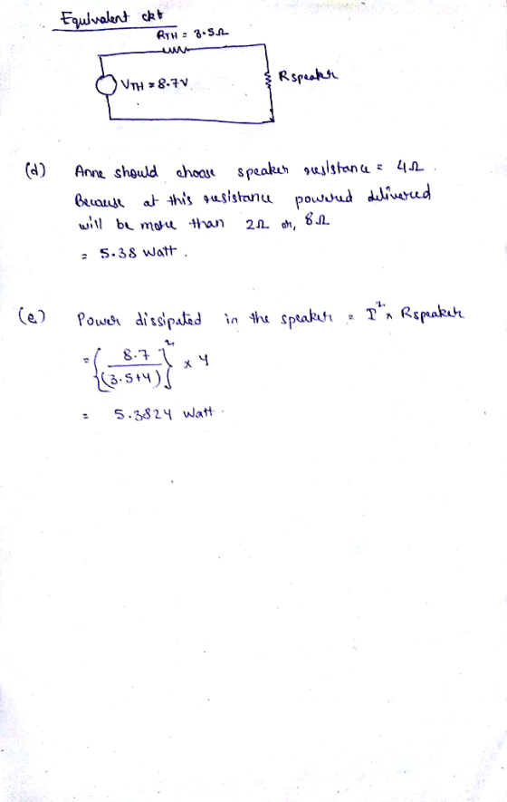
 The circuit shown in Figure Q4-1 includes an audio source and the equivalent circuit of a loudspeaker that you have been asked to analyse. 4. a) Assuming the speaker is to operate at a single frequency of 200 Hz and is5 driven by a cosinusoidal signal with peak amplitude of 20 V; determine the equivalent impedance of the speaker When connected to the audio source, calculate the current flow i() When testing the loudspeaker detailed in Q4a) i), you can...
 3- OPERATIONAL-AMPLIFIER Nominating ampliar Voltage Show OW Difference ampliar Wate Date amplizier Close R Vout Voutin Vout = vin Buffer = Inverting amplifier Dout = (1 + .. Vout V out 1 V2 ERR Vour (, - v3) Differential Amplifier Non-Inverting amplifier 1- Refer to the op amp in Fig. If v; = 0.5 V, calculate: (a) the output voltage Vos (b) the current in the 10-k! resistor. 25k92 10k02 Oo + 6 2. A 741 op amp has an...
 thanks
Laboratory 1: operation amplifier characteristics A. Objectives: 1. To study the basic characteristics of an operational amplifier 2. To study the bias circuit of an operational amplifier B. Apparatus: 1. DC Power supply 2. Experimental board and corresponding components 3. Electronic calculator (prepared by students) 4. Digital camera (prepared by students for photo taking of the experimental results) 5. Laptop computer with the software PicoScope 6 and Microsoft Word installed. 6. PicoScope PC Oscilloscope and its accessories. 7. Multimeter...
thanks
Laboratory 1: operation amplifier characteristics A. Objectives: 1. To study the basic characteristics of an operational amplifier 2. To study the bias circuit of an operational amplifier B. Apparatus: 1. DC Power supply 2. Experimental board and corresponding components 3. Electronic calculator (prepared by students) 4. Digital camera (prepared by students for photo taking of the experimental results) 5. Laptop computer with the software PicoScope 6 and Microsoft Word installed. 6. PicoScope PC Oscilloscope and its accessories. 7. Multimeter...
 QUESTION 1 Anna the Audiophile has asked for your help to build an amplifier and filter to take small signals from her hifi system and amplify them so that she can drive her new subwoofer. The hifi system produces AC signals at varying frequencies with 250mVrms maximum magnitude Her subwoofer requires the signals to be 20 Vrms maximum magnitude. The signals that Anna is interested in are below 200 Hz. She would like the filter to attenuate signals at frequencies...
 Question 1 In the diagram of Superheterodne AM receiver shown below explain the function of each block. (a) 15 marks Antenna Speaker Audio and power amplifiers RF IF Mixer Detector Mi amplifier amplifier AGC --_Local Gang tuned oscillator (b) For a 4-bit DAC, calculate the output voltage for an input code word 1010 if a [10 marks] logic 1 is 10V and a logic 0 is 0V, and R = RFI kΩ Total: 25 marks] Question 2 (a) Explain the...
 Q1. You are given a 12 V DC power supply. You are expected to develop a voltage divider to achieve a voltage of nominal 5V value using a pair of resistors from the E 12 range, with the restrition that you are not expected to draw a current of more than 1 mA from the 12 V DC supply i. Develop a simple circuit showing the possible values for each resistor pair, and the range of the DC output possible...
 (a) Design an inverting amplifier by choosing suitable resistor
values for R1 and R2 to produce a gain of 5 when both switches
Sw1 and Sw2 are open.
(b) Design the bias input circuit by choosing suitable resistors
R3 and R4 such that the voltage vb will be 0.5V if the
positive power supply of the op-amp is connected to a 5V battery.
Again both switches are open.
(c) Given Sw1 is open, the amplifier is turned on for
enough...
(a) Design an inverting amplifier by choosing suitable resistor
values for R1 and R2 to produce a gain of 5 when both switches
Sw1 and Sw2 are open.
(b) Design the bias input circuit by choosing suitable resistors
R3 and R4 such that the voltage vb will be 0.5V if the
positive power supply of the op-amp is connected to a 5V battery.
Again both switches are open.
(c) Given Sw1 is open, the amplifier is turned on for
enough...
 Yes, this is one problem. Please solve ALL PARTS. Guaranteed
thumbs up for the person who solves it.
3 1. Photodiode amplifier circuit You are designinga CF photosensor circuit for a light detection and ranging LiDAR) system in autonomous vehicles. The circuit utilizes a transimpedance amplifier to convert low-level RF photodiode current signal to a usable voltage output. It consists of a photodiode, an amplifier, and feedback capacitor/resistor pair as shown in Figure 1. We will derive simple equations to...
Yes, this is one problem. Please solve ALL PARTS. Guaranteed
thumbs up for the person who solves it.
3 1. Photodiode amplifier circuit You are designinga CF photosensor circuit for a light detection and ranging LiDAR) system in autonomous vehicles. The circuit utilizes a transimpedance amplifier to convert low-level RF photodiode current signal to a usable voltage output. It consists of a photodiode, an amplifier, and feedback capacitor/resistor pair as shown in Figure 1. We will derive simple equations to...
 The circuit shown in Figure Q4-1 includes an audio source and the equivalent circuit of a loudspeaker that you have been asked to analyse. 4. a) Assuming the speaker is to operate at a single frequency of 200 Hz and is5 driven by a cosinusoidal signal with peak amplitude of 20 V; determine the equivalent impedance of the speaker When connected to the audio source, calculate the current flow i() When testing the loudspeaker detailed in Q4a) i), you can...
Most questions answered within 3 hours.
-
Maths
asked 21 minutes ago -
Maths
asked 33 minutes ago -
1. You have genotyped an entire population of lab mice for a
single locus (let's label...
asked 1 hour ago -
As part of the process for improving the quality of their cars,
Toyota engineers have identified...
asked 1 hour ago -
What is the relationship between the number of coils in a
solenoid and the emf induced...
asked 1 hour ago -
cell in human body reproduces. what process does it use? describe
the steps in the cell...
asked 2 hours ago -
The cheetah is one of the fastest accelerating animals, for it
can go from rest to...
asked 3 hours ago -
CaCO3 (s) ⇌ CaO (s) + CO2 (g)
At 637 °C, the reaction reaches equilibrium.
If...
asked 4 hours ago -
The condensate from a steam distillation contains 12.0 g of
compound A and 18.0 g of...
asked 7 hours ago -
A major economic benefit of fixed exchange rates compared to
floating rates is that
a. the...
asked 7 hours ago -
1) For this reaction,
SiCl4 (l)+ 2H2O(g) <->
SiO2 (s) + 4HCl (g) DeltaH = -127 KJ...
asked 7 hours ago -
Which of the following does NOT add to US GDP? A. Saudi Arabia
buys fighter jets...
asked 9 hours ago