
Homework Answers
Add Answer to:
Esquivalent Resistance Current throughs R2 5. (10pts) A student collects a set of Current and Voltage...
The initial data set is given in the table below: R2 = 30 1, R2 =...
 The initial data set is given in the table below: R2 = 30 1, R2 = 40 1, R2 = 60 2, E; =3 V, E2 = 6 V 1, (in A) 0.061 1. (in A) 0.053 V (in V) 0.343 V in v 2.58 V: (in V) 3.2 L (in A) Experimental 0.105 Theoretical % Error Your job is to calculate all the theoretical values of currents and voltage drops for each resistor and then to compare them to...
Current A Voltage (10.01 V) (10.0001 A) Current B Current C (10.0001 A) (10.0001 A) 0.00...
 Current A Voltage (10.01 V) (10.0001 A) Current B Current C (10.0001 A) (10.0001 A) 0.00 0.0000 0.0000 0.0000 1.00 0.0079 0.0021 0.0107 2.00 0.0157 0.0041 0.0214 3.00 0.0236 0.0062 0.0321 A careless physics student collected current versus voltage measurements for three of four resistor circuits: Ri alone, R. alone, two resistors in series, and two resistors in parallel. However, this student failed to label the resistance for each situation, failed to record the data for one circuit, AND failed...
The circuit below can be used to simulate/measure the equivalent resistance of a circuit. The voltage...
 The circuit below can be used to simulate/measure the equivalent resistance of a circuit. The voltage from V, to ground will be the equivalent resistance because V-IR and in this case the current source ll is equal to 1 Amp. Note that in general Amp.s not used by a resistance meter as it can cause a too much power to be dissipated by the resistor which can burn out the resistor or change its value.) Create the circuit shown below...
Exercise #4 Voltage Divider A. Introduction In a previous exercise, you learned about the current-voltage relationship...
 Exercise #4 Voltage Divider A. Introduction In a previous exercise, you learned about the current-voltage relationship in a single resistor. Now, you will about how voltage is divided across two resistors in series. In this exercise you will: Examine the operation of the electric circuit known as the voltape divicder At the conclusion of this exercise you should be able to Compute the valtage across a resistor in a voltage divider circuit Design a voltage divider circuit to produce a...
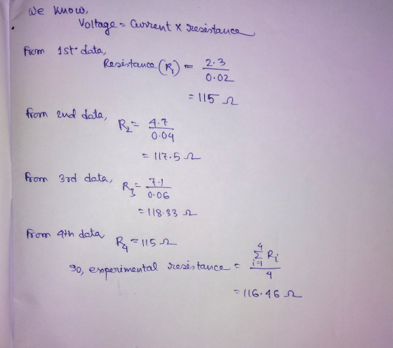
The voltage drop (V) across a resister is proportional to the current (I) through the resister. Ohm's Law: V = IR. Wednesday's laboratory expernnent attempts to verify Ohm's Law and...
 The voltage drop (V) across a resister is proportional to the current (I) through the resister. Ohm's Law: V = IR. Wednesday's laboratory expernnent attempts to verify Ohm's Law and measure the resistance (R) of a resister Ammeters and voltmeters potentially have offsets, resulting in a constant added to the equation: V = IR + VO If voltage satisfying this equation is plotted against current, the result is a line. With voltage on the y-axis and current on the r-axis,...
B Resistors in Parallel 12 Terminal Voltage V. (V) Current/, (A) Equiv. Resistance R. (12) Notes:...
 B Resistors in Parallel 12 Terminal Voltage V. (V) Current/, (A) Equiv. Resistance R. (12) Notes: 1. Prior to energizing circuit : Record the setting for each resistor. 2. Set up and energize each circuit shown below and record V, 1, 3. Measure and record V-V3, V, and/, -13,/p (see diagrams). 4. Calculate values in highlighted boxes based on measured values. 5. Copy and paste results of simulated circuits in the Multisim folder Current (A) Theoretical Voltage (V) Measured %...
2) A resistor of unknown resistance is connected to a power supply capable of producing electrical...
 2) A resistor of unknown resistance is connected to a power supply capable of producing electrical potentials from 0 volts to 10.0 volts. A student connects an ammeter in series with the power supply and resistor so that he can record the current flowing through the system. He produces the chart shown below. Potential Difference vs. Current M Potential Diff (V) 1.0 0.01 0.02 0.03 0.04 2.0 Current (A) 0.008 0.018 0.026 0.035 0.047 Current (A) 4.0 a. Label the...
V2 D2 LTL-307EE Q1 2N3904 Z1 R1 R2 Fig 01 The circuit shown in Fig 01 is useful to drive a load with a constant current independent of the supply voltage. In the given circuit load is considered as L...
 V2 D2 LTL-307EE Q1 2N3904 Z1 R1 R2 Fig 01 The circuit shown in Fig 01 is useful to drive a load with a constant current independent of the supply voltage. In the given circuit load is considered as LED. Following data is given Maximum possible current through LED is 30 mA Vz of Z1 is 3.3V R1 is 1 kQ Follow the steps given below: a). Assuming voltage V1 is large enough to operate Z1 in its operating region...
The current and voltage data are recorded below every 5 seconds for 1 minute (called a...
 The current and voltage data are recorded below every 5 seconds for 1 minute (called a minute test): time = 5:5:60; current = (16 25 32 40 45 47 44 40 33 26 20 11]; voltage = [2 5 4.5 4.7 5.5 5.4 4.2 3.9 3.3 3 2.8 2.1); a) Write a script that uses cubic equation to model both the current and voltage data as a function of time. The script will plot both sets of data points and...
ANALYSIS Use your experimental results to analyze the circuit in terms of Kirchhoff net current fow...
 ANALYSIS Use your experimental results to analyze the circuit in terms of Kirchhoff net current fow into and out of each of the four nodes, and determine whetheC s Rules. Consider supported by your data. Determine the net voltage drop around at leaston Sign determine whether or not your data supports the loop rule. (Pay close attosed loops convention.) In adition, verify ir Ohm's law is satisfied for at least three resistors and for the total reji >Q12: Why do...
 The initial data set is given in the table below: R2 = 30 1, R2 = 40 1, R2 = 60 2, E; =3 V, E2 = 6 V 1, (in A) 0.061 1. (in A) 0.053 V (in V) 0.343 V in v 2.58 V: (in V) 3.2 L (in A) Experimental 0.105 Theoretical % Error Your job is to calculate all the theoretical values of currents and voltage drops for each resistor and then to compare them to...
 Current A Voltage (10.01 V) (10.0001 A) Current B Current C (10.0001 A) (10.0001 A) 0.00 0.0000 0.0000 0.0000 1.00 0.0079 0.0021 0.0107 2.00 0.0157 0.0041 0.0214 3.00 0.0236 0.0062 0.0321 A careless physics student collected current versus voltage measurements for three of four resistor circuits: Ri alone, R. alone, two resistors in series, and two resistors in parallel. However, this student failed to label the resistance for each situation, failed to record the data for one circuit, AND failed...
 The circuit below can be used to simulate/measure the equivalent resistance of a circuit. The voltage from V, to ground will be the equivalent resistance because V-IR and in this case the current source ll is equal to 1 Amp. Note that in general Amp.s not used by a resistance meter as it can cause a too much power to be dissipated by the resistor which can burn out the resistor or change its value.) Create the circuit shown below...
 Exercise #4 Voltage Divider A. Introduction In a previous exercise, you learned about the current-voltage relationship in a single resistor. Now, you will about how voltage is divided across two resistors in series. In this exercise you will: Examine the operation of the electric circuit known as the voltape divicder At the conclusion of this exercise you should be able to Compute the valtage across a resistor in a voltage divider circuit Design a voltage divider circuit to produce a...
 The voltage drop (V) across a resister is proportional to the current (I) through the resister. Ohm's Law: V = IR. Wednesday's laboratory expernnent attempts to verify Ohm's Law and measure the resistance (R) of a resister Ammeters and voltmeters potentially have offsets, resulting in a constant added to the equation: V = IR + VO If voltage satisfying this equation is plotted against current, the result is a line. With voltage on the y-axis and current on the r-axis,...
 B Resistors in Parallel 12 Terminal Voltage V. (V) Current/, (A) Equiv. Resistance R. (12) Notes: 1. Prior to energizing circuit : Record the setting for each resistor. 2. Set up and energize each circuit shown below and record V, 1, 3. Measure and record V-V3, V, and/, -13,/p (see diagrams). 4. Calculate values in highlighted boxes based on measured values. 5. Copy and paste results of simulated circuits in the Multisim folder Current (A) Theoretical Voltage (V) Measured %...
 2) A resistor of unknown resistance is connected to a power supply capable of producing electrical potentials from 0 volts to 10.0 volts. A student connects an ammeter in series with the power supply and resistor so that he can record the current flowing through the system. He produces the chart shown below. Potential Difference vs. Current M Potential Diff (V) 1.0 0.01 0.02 0.03 0.04 2.0 Current (A) 0.008 0.018 0.026 0.035 0.047 Current (A) 4.0 a. Label the...
 V2 D2 LTL-307EE Q1 2N3904 Z1 R1 R2 Fig 01 The circuit shown in Fig 01 is useful to drive a load with a constant current independent of the supply voltage. In the given circuit load is considered as LED. Following data is given Maximum possible current through LED is 30 mA Vz of Z1 is 3.3V R1 is 1 kQ Follow the steps given below: a). Assuming voltage V1 is large enough to operate Z1 in its operating region...
 The current and voltage data are recorded below every 5 seconds for 1 minute (called a minute test): time = 5:5:60; current = (16 25 32 40 45 47 44 40 33 26 20 11]; voltage = [2 5 4.5 4.7 5.5 5.4 4.2 3.9 3.3 3 2.8 2.1); a) Write a script that uses cubic equation to model both the current and voltage data as a function of time. The script will plot both sets of data points and...
 ANALYSIS Use your experimental results to analyze the circuit in terms of Kirchhoff net current fow into and out of each of the four nodes, and determine whetheC s Rules. Consider supported by your data. Determine the net voltage drop around at leaston Sign determine whether or not your data supports the loop rule. (Pay close attosed loops convention.) In adition, verify ir Ohm's law is satisfied for at least three resistors and for the total reji >Q12: Why do...
Most questions answered within 3 hours.
-
Accent Software faces the following conditions. All of these
support Accent’s use of a market-penetration pricing...
asked 11 minutes ago -
A mathematically inclined friend emails you the following
instructions: "Meet me in the cafeteria the first...
asked 14 minutes ago -
A monopoly sells in two countries . The demand curves in the two
countries are p1...
asked 1 hour ago -
A .15kg rubber ball is bounced off a wall. Before hitting the
wall, the ball moves...
asked 1 hour ago -
A manufacturing company preparing to build a new plant is
considering three potential locations for it....
asked 1 hour ago -
B. If compound Y has approximately the same values of solubility
in toluene as compound X,...
asked 2 hours ago -
Oscar Inc. has inventory in Japan valued at 39,051,000 Yen one
year ago. One year ago...
asked 2 hours ago -
If Canada suffered from "fundamental disequilibrium," and its
government choose not to devalue its currency, a...
asked 2 hours ago -
4. How many input & output Key Value Pairs are passed into,
and emitted out of...
asked 2 hours ago -
Why would your heart not function well if constructed of
skeletal muscle? What is the particular...
asked 2 hours ago -
Please respond to this essay question in full essay form for
Chemistry 1102 Organic and Biochemistry:...
asked 2 hours ago -
Determine the head loss and velocity of flow in a water supply main
of 15.0 cm...
asked 3 hours ago