
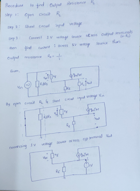
can someone show me how to do this please
i think i was taught that when i want to find the output resistance then all i need to do is short circuit the input voltage and add a nominal voltage attached to Vout inorder relate with ohms law to find output resistance
thank you
Homework Answers
 kindly see the above images
for the solution.
kindly see the above images
for the solution.
Add Answer to:
can someone show me how to do this please
i think i was taught that when...
Find the Steady State Voltage and Current Values. Develop the equation for i(t) , the current thr...
 Find the Steady State Voltage and Current
Values.
Develop the equation for i(t) , the current through
the inductor and Vout(t).
I need help, I don't know if my calculations are correct, I
found the neper frequency to be: a=439.109 rad/sec and resonant
frequency to be Wo=14586.5 rad/sec.
This is a parallel step response RLC circuit
The circuit is underdamped.
Please show all work clearly so that I can understand the
process.
Vout(t) is the voltage across R2 (which is...
Find the Steady State Voltage and Current
Values.
Develop the equation for i(t) , the current through
the inductor and Vout(t).
I need help, I don't know if my calculations are correct, I
found the neper frequency to be: a=439.109 rad/sec and resonant
frequency to be Wo=14586.5 rad/sec.
This is a parallel step response RLC circuit
The circuit is underdamped.
Please show all work clearly so that I can understand the
process.
Vout(t) is the voltage across R2 (which is...
can someone help me with part c mpt tope alswersol the sdme part of you willbe penalized for this. Question 1 1 pts For the circuit shown in Figure 6.49, let Vcc -9V.RE 0.11 kQ, R1 3.6 k2, R2 5.6...
 can someone help me with part c
mpt tope alswersol the sdme part of you willbe penalized for this. Question 1 1 pts For the circuit shown in Figure 6.49, let Vcc -9V.RE 0.11 kQ, R1 3.6 k2, R2 5.6k(2, and Rs -o Ω . The transistor parameters are β-200. VBE(On)-Q7V, VA - 100 V and VT 0.026 V.(a) Determine the quiescent value of lEQ. (b) Find the small-signal voltage gain Av-vo/vg (c) Determine the output resistance Ro looking into...
can someone help me with part c
mpt tope alswersol the sdme part of you willbe penalized for this. Question 1 1 pts For the circuit shown in Figure 6.49, let Vcc -9V.RE 0.11 kQ, R1 3.6 k2, R2 5.6k(2, and Rs -o Ω . The transistor parameters are β-200. VBE(On)-Q7V, VA - 100 V and VT 0.026 V.(a) Determine the quiescent value of lEQ. (b) Find the small-signal voltage gain Av-vo/vg (c) Determine the output resistance Ro looking into...
shows two versions of a common-emitter amplifier and (i Fig. 1 (a) Find the expression for the small-signal voltage gai...
 shows two versions of a common-emitter amplifier and (i Fig. 1 (a) Find the expression for the small-signal voltage gain of Fig. 1(i) in terms of relevant small- signal parameters. (b) Over what frequency range will the gain of the Fig. 1(i) circuit be the same as that of the Fig. 1(i) circuit? (c) Which of the two circuits will show less variation in its de biasing in the presence of processing or temperature variations? Justify your answer. (d) Explain,...
show steps please Find the output voltage Vout, and the current i, in the circuit in...
 show steps please
Find the output voltage Vout, and the current i, in the circuit in Fig.1 below. HINT: VA = 0. R2 10K 12 M R1 = 2K2 w Va 1V Vout R3 = 3K 12 Fig. 1
show steps please
Find the output voltage Vout, and the current i, in the circuit in Fig.1 below. HINT: VA = 0. R2 10K 12 M R1 = 2K2 w Va 1V Vout R3 = 3K 12 Fig. 1
To obtain the difference between two different inputs, we can connect them to the positive and...
 To obtain the difference between two different inputs, we can connect them to the positive and negative pins of the Opamp. R1 7 +15V - opamp Ra AL15V Vout = 2 (U2-01) Where, R=R3 R2RA Figure 6: The difference amplifier The voltage follower is a non-inverting amplifier configuration with a gain of unity. Its output basically “follows” its input. The voltage follower's main virtue is that it has a very high input resistance. This is useful for driving a low...
shows two versions of a common-emitter amplifier and (i Fig. 1 (a) Find the expression for...
 shows two versions of a common-emitter amplifier and (i Fig. 1 (a) Find the expression for the small-signal voltage gain of Fig. 1(i) in terms of relevant small- signal parameters. (b) Over what frequency range will the gain of the Fig. 1(i) circuit be the same as that of the Fig. 1(i) circuit? (c) Which of the two circuits will show less variation in its de biasing in the presence of processing or temperature variations? Justify your answer. (d) Explain,...
For the circuit shown below, let Vcc 9 V R2 RE-0.11 kQ, R1 3.6 k2. and R2 -5.6 kQ. The transistor parameters are β-200, VBE(on)-OTV, VA-100 V and VT = 0.026 V. (a) Determine the quiescent value o...
 For the circuit shown below, let Vcc 9 V R2 RE-0.11 kQ, R1 3.6 k2. and R2 -5.6 kQ. The transistor parameters are β-200, VBE(on)-OTV, VA-100 V and VT = 0.026 V. (a) Determine the quiescent value of IEQ (b) Find the small-signal voltage gain Av Vo/vs (c) Determine the output resistance R, looking into output terminals Av= 0.5589 Ro-0.4688 Ω Ro-0.9118 Ω leQ- 23.76 mA Ra " 0.6538 Ω leo 39.52 mA A, 0.9938
For the circuit shown below,...
For the circuit shown below, let Vcc 9 V R2 RE-0.11 kQ, R1 3.6 k2. and R2 -5.6 kQ. The transistor parameters are β-200, VBE(on)-OTV, VA-100 V and VT = 0.026 V. (a) Determine the quiescent value of IEQ (b) Find the small-signal voltage gain Av Vo/vs (c) Determine the output resistance R, looking into output terminals Av= 0.5589 Ro-0.4688 Ω Ro-0.9118 Ω leQ- 23.76 mA Ra " 0.6538 Ω leo 39.52 mA A, 0.9938
For the circuit shown below,...
4. For the amplifier in the figure below use the parameters in the table: +Vcc Re VBE- 0.7V, Ri- ...
 4. For the amplifier in the figure below use the parameters in the table: +Vcc Re VBE- 0.7V, Ri- 1002, R1-160k2, R2-320k2 R3-200k2, R6-40 k2, Rc-60k2, Vcc- 12V, Ry Do a) Draw the DC equivalent circuit and calculate the Q-point. c) Draw the AC equivalent circuit with the small signal model for the transistor. d) Calculate the voltage gain, Av-Vo/vi. Assume ro infinite. e) Draw the circuit to find the amplifier input resistance (Rin). Calculate Rin f Draw the circuit...
Please answer full question thoroughly (A & B) showing detailed work. Double check answer and work...
 Please answer full question thoroughly (A & B)
showing detailed work. Double check answer and work to ensure it is
correct for thumbs up
Part A
Part B
Consider the following circuit of five resistors connected to a DC power supply set to 1.0V R1 R2 R3 V1 U 1V R4 R5 R1 0.05 ohms, R2 0.2 ohms, R3 99 ohms and R5 0.15 ohms. The voltage drop across R4 is 6 mV. Answer the following: What is the current...
Please answer full question thoroughly (A & B)
showing detailed work. Double check answer and work to ensure it is
correct for thumbs up
Part A
Part B
Consider the following circuit of five resistors connected to a DC power supply set to 1.0V R1 R2 R3 V1 U 1V R4 R5 R1 0.05 ohms, R2 0.2 ohms, R3 99 ohms and R5 0.15 ohms. The voltage drop across R4 is 6 mV. Answer the following: What is the current...
Do not answer it , if you do not know how to use pspice
 do not answer it , if you do not know how to use pspice
Vc 15Vdc R2 Rc 5k 150 C2 01 C1 RL 02N2222 Vin 50k R1 Re VAMP L-50mV FREQ 5000Hz Ce 10uF 1k 50 Figure 1: A Common-Emitter Amplifier Circuit Configuration 4. Refer to Fig. 1 in the handout; simulate the circuit in PSpice and obtain the input-output waveforms (to calculate the voltage gain) for a sinusoidal input with a magnitude of 10 mV and the frequencies...
do not answer it , if you do not know how to use pspice
Vc 15Vdc R2 Rc 5k 150 C2 01 C1 RL 02N2222 Vin 50k R1 Re VAMP L-50mV FREQ 5000Hz Ce 10uF 1k 50 Figure 1: A Common-Emitter Amplifier Circuit Configuration 4. Refer to Fig. 1 in the handout; simulate the circuit in PSpice and obtain the input-output waveforms (to calculate the voltage gain) for a sinusoidal input with a magnitude of 10 mV and the frequencies...
 Find the Steady State Voltage and Current
Values.
Develop the equation for i(t) , the current through
the inductor and Vout(t).
I need help, I don't know if my calculations are correct, I
found the neper frequency to be: a=439.109 rad/sec and resonant
frequency to be Wo=14586.5 rad/sec.
This is a parallel step response RLC circuit
The circuit is underdamped.
Please show all work clearly so that I can understand the
process.
Vout(t) is the voltage across R2 (which is...
Find the Steady State Voltage and Current
Values.
Develop the equation for i(t) , the current through
the inductor and Vout(t).
I need help, I don't know if my calculations are correct, I
found the neper frequency to be: a=439.109 rad/sec and resonant
frequency to be Wo=14586.5 rad/sec.
This is a parallel step response RLC circuit
The circuit is underdamped.
Please show all work clearly so that I can understand the
process.
Vout(t) is the voltage across R2 (which is...
 can someone help me with part c
mpt tope alswersol the sdme part of you willbe penalized for this. Question 1 1 pts For the circuit shown in Figure 6.49, let Vcc -9V.RE 0.11 kQ, R1 3.6 k2, R2 5.6k(2, and Rs -o Ω . The transistor parameters are β-200. VBE(On)-Q7V, VA - 100 V and VT 0.026 V.(a) Determine the quiescent value of lEQ. (b) Find the small-signal voltage gain Av-vo/vg (c) Determine the output resistance Ro looking into...
can someone help me with part c
mpt tope alswersol the sdme part of you willbe penalized for this. Question 1 1 pts For the circuit shown in Figure 6.49, let Vcc -9V.RE 0.11 kQ, R1 3.6 k2, R2 5.6k(2, and Rs -o Ω . The transistor parameters are β-200. VBE(On)-Q7V, VA - 100 V and VT 0.026 V.(a) Determine the quiescent value of lEQ. (b) Find the small-signal voltage gain Av-vo/vg (c) Determine the output resistance Ro looking into...
 shows two versions of a common-emitter amplifier and (i Fig. 1 (a) Find the expression for the small-signal voltage gain of Fig. 1(i) in terms of relevant small- signal parameters. (b) Over what frequency range will the gain of the Fig. 1(i) circuit be the same as that of the Fig. 1(i) circuit? (c) Which of the two circuits will show less variation in its de biasing in the presence of processing or temperature variations? Justify your answer. (d) Explain,...
 show steps please
Find the output voltage Vout, and the current i, in the circuit in Fig.1 below. HINT: VA = 0. R2 10K 12 M R1 = 2K2 w Va 1V Vout R3 = 3K 12 Fig. 1
show steps please
Find the output voltage Vout, and the current i, in the circuit in Fig.1 below. HINT: VA = 0. R2 10K 12 M R1 = 2K2 w Va 1V Vout R3 = 3K 12 Fig. 1
 To obtain the difference between two different inputs, we can connect them to the positive and negative pins of the Opamp. R1 7 +15V - opamp Ra AL15V Vout = 2 (U2-01) Where, R=R3 R2RA Figure 6: The difference amplifier The voltage follower is a non-inverting amplifier configuration with a gain of unity. Its output basically “follows” its input. The voltage follower's main virtue is that it has a very high input resistance. This is useful for driving a low...
 shows two versions of a common-emitter amplifier and (i Fig. 1 (a) Find the expression for the small-signal voltage gain of Fig. 1(i) in terms of relevant small- signal parameters. (b) Over what frequency range will the gain of the Fig. 1(i) circuit be the same as that of the Fig. 1(i) circuit? (c) Which of the two circuits will show less variation in its de biasing in the presence of processing or temperature variations? Justify your answer. (d) Explain,...
 For the circuit shown below, let Vcc 9 V R2 RE-0.11 kQ, R1 3.6 k2. and R2 -5.6 kQ. The transistor parameters are β-200, VBE(on)-OTV, VA-100 V and VT = 0.026 V. (a) Determine the quiescent value of IEQ (b) Find the small-signal voltage gain Av Vo/vs (c) Determine the output resistance R, looking into output terminals Av= 0.5589 Ro-0.4688 Ω Ro-0.9118 Ω leQ- 23.76 mA Ra " 0.6538 Ω leo 39.52 mA A, 0.9938
For the circuit shown below,...
For the circuit shown below, let Vcc 9 V R2 RE-0.11 kQ, R1 3.6 k2. and R2 -5.6 kQ. The transistor parameters are β-200, VBE(on)-OTV, VA-100 V and VT = 0.026 V. (a) Determine the quiescent value of IEQ (b) Find the small-signal voltage gain Av Vo/vs (c) Determine the output resistance R, looking into output terminals Av= 0.5589 Ro-0.4688 Ω Ro-0.9118 Ω leQ- 23.76 mA Ra " 0.6538 Ω leo 39.52 mA A, 0.9938
For the circuit shown below,...
 4. For the amplifier in the figure below use the parameters in the table: +Vcc Re VBE- 0.7V, Ri- 1002, R1-160k2, R2-320k2 R3-200k2, R6-40 k2, Rc-60k2, Vcc- 12V, Ry Do a) Draw the DC equivalent circuit and calculate the Q-point. c) Draw the AC equivalent circuit with the small signal model for the transistor. d) Calculate the voltage gain, Av-Vo/vi. Assume ro infinite. e) Draw the circuit to find the amplifier input resistance (Rin). Calculate Rin f Draw the circuit...
 Please answer full question thoroughly (A & B)
showing detailed work. Double check answer and work to ensure it is
correct for thumbs up
Part A
Part B
Consider the following circuit of five resistors connected to a DC power supply set to 1.0V R1 R2 R3 V1 U 1V R4 R5 R1 0.05 ohms, R2 0.2 ohms, R3 99 ohms and R5 0.15 ohms. The voltage drop across R4 is 6 mV. Answer the following: What is the current...
Please answer full question thoroughly (A & B)
showing detailed work. Double check answer and work to ensure it is
correct for thumbs up
Part A
Part B
Consider the following circuit of five resistors connected to a DC power supply set to 1.0V R1 R2 R3 V1 U 1V R4 R5 R1 0.05 ohms, R2 0.2 ohms, R3 99 ohms and R5 0.15 ohms. The voltage drop across R4 is 6 mV. Answer the following: What is the current...
 do not answer it , if you do not know how to use pspice
Vc 15Vdc R2 Rc 5k 150 C2 01 C1 RL 02N2222 Vin 50k R1 Re VAMP L-50mV FREQ 5000Hz Ce 10uF 1k 50 Figure 1: A Common-Emitter Amplifier Circuit Configuration 4. Refer to Fig. 1 in the handout; simulate the circuit in PSpice and obtain the input-output waveforms (to calculate the voltage gain) for a sinusoidal input with a magnitude of 10 mV and the frequencies...
do not answer it , if you do not know how to use pspice
Vc 15Vdc R2 Rc 5k 150 C2 01 C1 RL 02N2222 Vin 50k R1 Re VAMP L-50mV FREQ 5000Hz Ce 10uF 1k 50 Figure 1: A Common-Emitter Amplifier Circuit Configuration 4. Refer to Fig. 1 in the handout; simulate the circuit in PSpice and obtain the input-output waveforms (to calculate the voltage gain) for a sinusoidal input with a magnitude of 10 mV and the frequencies...
Most questions answered within 3 hours.
-
1. When a nearsighted person looks at an object that is in the
distance with their...
asked 1 minute ago -
QUESTION 8
Both of these statements will store the same value in the
variable $number
$number...
asked 25 minutes ago -
The price of 1 lb of potatoes is $1.75. If all the potatoes sold
today at...
asked 1 hour ago -
Garcia Company issues 20.00%, 15-year bonds with a par value of
$470,000 and semiannual interest payments....
asked 1 hour ago -
In C++ Programming, Try using loops only.
This lab demonstrates the use of the While Loop...
asked 2 hours ago -
Effect of DCMU and sodium azide on Chlamydomonas? We did an
experiment where we had Chlamydomonas...
asked 2 hours ago -
1a) According to the ideal gas law, _______________.
a. a gas has infinite volume at absolute...
asked 4 hours ago -
Oakdale Fashions, Inc. had $245,000 in 2018 taxable income.
Using the tax schedule in Table 2.3...
asked 4 hours ago -
The marketing class at CSUS had an average score of 150. An
educational analyst determined that...
asked 5 hours ago -
Justin Case has purchased a $250 000 home by putting 20 % down
and taking out...
asked 6 hours ago -
1. In a labor market, marginal cost for a firm is
____________.
a. recruiting cost
b....
asked 6 hours ago -
On January 1, 2019, ABC Company issued $60,000,000 of 20-year,
10.5% bonds when the market rate...
asked 7 hours ago