
Homework Answers


Add Answer to:
16) For the Circuit in Figure 4, determine the Thevenin Voltage, Vw, seen by the load,...
2. Determine the open-circuit voltage, the short-circuit current, the Thevenin equivalent, and the Norton equivalent with...
 2. Determine the open-circuit voltage, the short-circuit current, the Thevenin equivalent, and the Norton equivalent with respect to the terminals a and b in the circuit shown. 1kΩ a 1k02 4k92 Va 2k2 6k 2 5iz 5V 2kΩ 3 2va 4V 6kΩΣ lui page 1 C Search or typ esc # # a % $
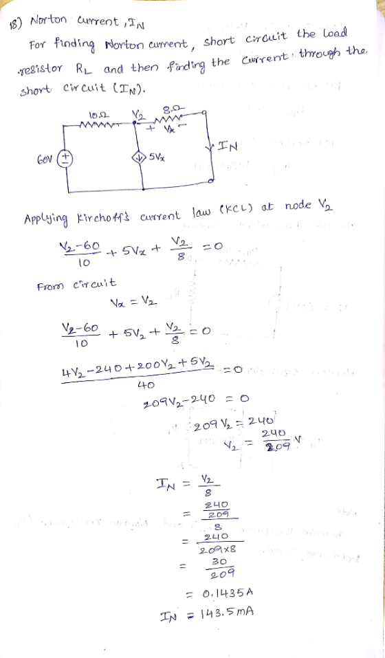
[p2bs 20q6a] The Thevenin or open circuit voltage "seen by" the load resistor RL is most...
 [p2bs 20q6a] The Thevenin or open circuit voltage "seen by" the load resistor RL is most nearly 2.4 KS2 1.6 ks2 L w 60 v +1 sa 24.8 k2 15 ma 25k2 : SRL W 1.8 ks2 6V None of the other answers 8V 10 V At
Figure 3 Transistor amplifire circuit with source Vs and load R b) For the BJT switching...
 Figure 3 Transistor amplifire circuit with source Vs and load R b) For the BJT switching circuit shown in Figure 4, i) Calculate the value of Ra so that the transistor is operating in saturation when switched on if the value of Rc is 3.9 kn. ii) What will the output voltage be for the applied input signal voltage shown if Vcet IS 0.2V? 5 V Re o V 5 V B 100 OV Figure 4 BUT switching circuit with...
4. Determine the Thevenin and Norton equivalents (Rth, RN, Vrh, and In) for the circuit shown...
 4. Determine the Thevenin and Norton equivalents (Rth, RN, Vrh, and In) for the circuit shown below at terminals a-b. 4 A 49 82 w 2 31022 w 48 V
Mini-Prj 2. Extraction of Thevenin and Norton Equivalent Circuits by LTspice Part B. Wheatstone B...
 Mini-Prj 2. Extraction of Thevenin and Norton Equivalent Circuits by LTspice Part B. Wheatstone Bridge Circuit with a Current Source Is R5 R1 R2 Is RL R3 R4 For the circuit as shown below, given that R1-22 Ω, R2-15 Ω, R3-28 Ω, R4-9 Ω, R5-29 Ω , R.-16 Ω, 1,-6 A. I. Wheatstone Bridge Circuit Analysis (a) Determining the load voltage VL-Vab for the Wheatstone bridge circuit with LTspice. Submit Answer Tries 0/4 (b) Determining the load current IL following...
Mini-Prj 2. Extraction of Thevenin and Norton Equivalent Circuits by LTspice Part A. Wheatstone B...
 Mini-Prj 2. Extraction of Thevenin and Norton Equivalent Circuits by LTspice Part A. Wheatstone Bridge Circuit with a Voltage Source Vs R5 R1 R2 Vs RL R3 R4 For the circuit as shown below, given that R1= 9 Ω, R2= 17 Ω, R3= 9 Ω' R,-18 Ω, R5= 19 Ω , RL= 2 Ω ,V,-74 V I. Wheatstone Bridge Circuit Analysis (a) Determining the load voltage Vi-Vab for the Wheatstone bridge circuit with LTspice Submit Answer Tries 0/3 (b) Determining...
Problem #4 In the voltage-divider circuit shown in Figure, the no-load value of y, is 4...
 Problem #4 In the voltage-divider circuit shown in Figure, the no-load value of y, is 4 V. When the load resistance R, is attached across the terminals a and b, v, drops to 3V. Find R 40.2 w 20 V 20v & R2 vo {RL
Problem 4.71 Part A A Thevenin equivalent can also be determined from measurements made at the...
 Problem 4.71 Part A A Thevenin equivalent can also be determined from measurements made at the pair of terminals of interest. Assume the following measurements were made at the terminals a,b in the circuit in the figure. When a 2012 resistor is connected to the terminals a,b, the voltage Wab is measured and found to be 120 V When a 502 resistor is connected to the terminals a,b, the voltage is measured and found to be 159 V. (Figure 1)...
Q1. 6V Suppose R3 is the load (R) in above circuit. 1. Mark terminals a and...
 Q1. 6V Suppose R3 is the load (R) in above circuit. 1. Mark terminals a and b of the THEVENIN equivalent on the original circuit. 2. Determine Rth and Eth. 3. Determine V on R3. 4. Calculate the power dissipated by R3. 5. What is the maximum power that can be delivered by the THÉVENIN equivalent circuit? 6. What is the R3 value when the output power is at Maximum?
29. Identify the type of third stage amplifier: a) inverting amplifier; b) differential amplifier with passi load; c) differential amplifier with current mirror load; d) emitter follower; e...
 29. Identify the type of third stage amplifier: a) inverting amplifier; b) differential amplifier with passi load; c) differential amplifier with current mirror load; d) emitter follower; e) none of above; 30. The Vsg of Q5 should be: a)-1V, b)-0.85% c) 0.65% d)0.85% env 31. To obtain IREF-30μΑ , the value of R should be: a)250ohm; b)25Kohm; c)250Kohm; d)2.5Mohm; e 5Mohm. network is composed by 4 identical phase shifter. The phase shift of each phase shifter in degree should be...
 2. Determine the open-circuit voltage, the short-circuit current, the Thevenin equivalent, and the Norton equivalent with respect to the terminals a and b in the circuit shown. 1kΩ a 1k02 4k92 Va 2k2 6k 2 5iz 5V 2kΩ 3 2va 4V 6kΩΣ lui page 1 C Search or typ esc # # a % $
 [p2bs 20q6a] The Thevenin or open circuit voltage "seen by" the load resistor RL is most nearly 2.4 KS2 1.6 ks2 L w 60 v +1 sa 24.8 k2 15 ma 25k2 : SRL W 1.8 ks2 6V None of the other answers 8V 10 V At
 Figure 3 Transistor amplifire circuit with source Vs and load R b) For the BJT switching circuit shown in Figure 4, i) Calculate the value of Ra so that the transistor is operating in saturation when switched on if the value of Rc is 3.9 kn. ii) What will the output voltage be for the applied input signal voltage shown if Vcet IS 0.2V? 5 V Re o V 5 V B 100 OV Figure 4 BUT switching circuit with...
 4. Determine the Thevenin and Norton equivalents (Rth, RN, Vrh, and In) for the circuit shown below at terminals a-b. 4 A 49 82 w 2 31022 w 48 V
 Mini-Prj 2. Extraction of Thevenin and Norton Equivalent Circuits by LTspice Part B. Wheatstone Bridge Circuit with a Current Source Is R5 R1 R2 Is RL R3 R4 For the circuit as shown below, given that R1-22 Ω, R2-15 Ω, R3-28 Ω, R4-9 Ω, R5-29 Ω , R.-16 Ω, 1,-6 A. I. Wheatstone Bridge Circuit Analysis (a) Determining the load voltage VL-Vab for the Wheatstone bridge circuit with LTspice. Submit Answer Tries 0/4 (b) Determining the load current IL following...
 Mini-Prj 2. Extraction of Thevenin and Norton Equivalent Circuits by LTspice Part A. Wheatstone Bridge Circuit with a Voltage Source Vs R5 R1 R2 Vs RL R3 R4 For the circuit as shown below, given that R1= 9 Ω, R2= 17 Ω, R3= 9 Ω' R,-18 Ω, R5= 19 Ω , RL= 2 Ω ,V,-74 V I. Wheatstone Bridge Circuit Analysis (a) Determining the load voltage Vi-Vab for the Wheatstone bridge circuit with LTspice Submit Answer Tries 0/3 (b) Determining...
 Problem #4 In the voltage-divider circuit shown in Figure, the no-load value of y, is 4 V. When the load resistance R, is attached across the terminals a and b, v, drops to 3V. Find R 40.2 w 20 V 20v & R2 vo {RL
 Problem 4.71 Part A A Thevenin equivalent can also be determined from measurements made at the pair of terminals of interest. Assume the following measurements were made at the terminals a,b in the circuit in the figure. When a 2012 resistor is connected to the terminals a,b, the voltage Wab is measured and found to be 120 V When a 502 resistor is connected to the terminals a,b, the voltage is measured and found to be 159 V. (Figure 1)...
 Q1. 6V Suppose R3 is the load (R) in above circuit. 1. Mark terminals a and b of the THEVENIN equivalent on the original circuit. 2. Determine Rth and Eth. 3. Determine V on R3. 4. Calculate the power dissipated by R3. 5. What is the maximum power that can be delivered by the THÉVENIN equivalent circuit? 6. What is the R3 value when the output power is at Maximum?
 29. Identify the type of third stage amplifier: a) inverting amplifier; b) differential amplifier with passi load; c) differential amplifier with current mirror load; d) emitter follower; e) none of above; 30. The Vsg of Q5 should be: a)-1V, b)-0.85% c) 0.65% d)0.85% env 31. To obtain IREF-30μΑ , the value of R should be: a)250ohm; b)25Kohm; c)250Kohm; d)2.5Mohm; e 5Mohm. network is composed by 4 identical phase shifter. The phase shift of each phase shifter in degree should be...
Most questions answered within 3 hours.
-
1.b. Fiscal policy is said to suffer from ‘crowding out’.
Explain what this means and why...
asked 2 minutes ago -
The equation for the reaction of nitrogen and oxygen to form
nitrogen oxide is written as...
asked 6 minutes ago -
A scientist reproducing some photoelectric effect experiments
shines a light on a metal electrode, but doesn't...
asked 9 minutes ago -
In a study designed to test the effectiveness of magnets for
treating back pain, 35 patients...
asked 29 minutes ago -
Here are summary statistics for randomly selected weights of
newborn girls:
nequals=193,
x overbarxequals=30.5
hg,
sequals=7.3...
asked 18 minutes ago -
Exercise #3:
Create the “MathTest” class. It will have two class variables:
1) a question and...
asked 21 minutes ago -
In epidemiology, how do you calculate the overall incidence of
cure within two groups? What formula...
asked 25 minutes ago -
A 1 liter solution contains 0.357 M ammonium chloride and 0.268
M ammonia. Addition of 0.295...
asked 26 minutes ago -
What are the advantages and disadvantages of using virtual
reality simulations in health care education?
asked 31 minutes ago -
Given input { 66, 28, 43, 29, 44, 69, 19 } and a hash function
h(x)...
asked 52 minutes ago -
A pebble with mass m is thrown straight up with an initial speed
v0 so that...
asked 55 minutes ago -
Let X be a discrete random variable that follows a
binomial distribution with n = 11...
asked 1 hour ago