Please Solve #27/28 correctly!!!
* #27 is NOT 0.786 MPa
* #28 is NOT 500.023 mm
attached is work for #24-26 if needed for #27/28
attached is previous #27/28 submission that was incorrect


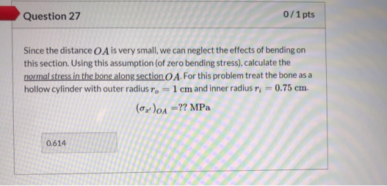
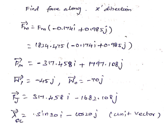
![Question 24 1/1 pts Calculate the magnitude of the force in the deltoid muscle [Fm] =??N 1,824.475 1/1 pts Question 25 Calcul](http://img.homeworklib.com/questions/73ba3d90-f9b5-11eb-af9b-c130e88d649f.png?x-oss-process=image/resize,w_560)

Homework Answers


Add Answer to:
Please Solve #27/28 correctly!!!
* #27 is NOT 0.786 MPa
* #28 is NOT 500.023 mm...
#27, #31 & #35 Only In Exercises 27-38, solve each equation for θ in the i...
 #27, #31 & #35 Only
In Exercises 27-38, solve each equation for θ in the i [0°, 360°). If necessary, write your answer to the ne of a degree. nearest tenth tenth 4 sin 2θ 28, 1 27/ 3 cos 29-1 30. 2 sin 30 12 32. 4 cos 30 1 0 2 29, 2 cos3θ + 1 31. 3 sin 30 +10 34. 2 cos V3 0 33. 2 sin1 0 35 2 sec 20 +37
#27, #31 & #35 Only
In Exercises 27-38, solve each equation for θ in the i [0°, 360°). If necessary, write your answer to the ne of a degree. nearest tenth tenth 4 sin 2θ 28, 1 27/ 3 cos 29-1 30. 2 sin 30 12 32. 4 cos 30 1 0 2 29, 2 cos3θ + 1 31. 3 sin 30 +10 34. 2 cos V3 0 33. 2 sin1 0 35 2 sec 20 +37
(A) 8 mm 100 mm Problem 1 (20 pts): Stress Concentrations Consider the flat bar with...
 (A) 8 mm 100 mm Problem 1 (20 pts): Stress Concentrations Consider the flat bar with shoulder joints shown in Fig. A which is subjected to a tensile force P = 58 kN. The bar is made of Aluminum 6061 having maximum tensile strength Omax = 290 MPa. NOTE: plots of stress concentration factors for different types of loading can be found on page 6. (a) Determine the radius r [mm] for the fillets. (b) An identical flat bar shown...
(A) Smin 100 mm Problem 1 (20 pts): Stress Concentrations Consider the flat bar with shoulder...
 (A) Smin 100 mm Problem 1 (20 pts): Stress Concentrations Consider the flat bar with shoulder joints shown in Fig. A which is subjected to a tensile force P = 58 kN. The bar is made of Aluminum 6061 having maximum tensile strength Omax = 290 MPa. NOTE: plots of stress concentration factors for different types of loading can be found on page 6 (a) Determine the radius r [mm] for the fillets. (b) An identical flat bar shown in...
S = 200 kpsi A steel shaft in bending has an ultimate strength of 690 MPa...
 S = 200 kpsi A steel shaft in bending has an ultimate strength of 690 MPa and a shoulder with a filler radius of 3 mm connecting a 32 mm diameter with a 38 mm diameter. Estimate the fatigue stress concentration factor, Kf, using Figure 6-20. 0 0.5 1.0 3.0 3.5 4.0 1.0 Notch radius r, mm 1.5 2.0 2.5 (1.4 GPa) (1.0) (0.7) 0.8 150 (0.4) 100 0.6 60 Notch sensitivity a 0.4 Steels Alum, alloy 0.2 0 0...
A steel shaft in bending has an ultimate strength of 1400 MPa and a shoulder with...
 A steel shaft in bending has an ultimate strength of 1400 MPa and a shoulder with a filler radius of 0.5 mm connecting an 18 mm diameter with a 19 mm diameter. Estimate the fatigue stress concentration factor, Kf, using Figure 6-20, 0 0.5 1.0 3.0 3.5 4.0 Notch radius r, mm 1.5 2.0 2.5 (1.4 GPa) (1.0) 1.0 Su = 200 kpsi (0.7) 0.8 150 (0.4) 100 0.6 60 Notch sensitivity 9 0.4 Steels Alum, alloy 0.2 0 0...
Rotational Dynamics Assignment (200 Points) • Due Friday, July 31 at 5:00 pm Equations are in...
 Rotational Dynamics Assignment (200 Points) • Due Friday, July 31 at 5:00 pm Equations are in a separate document entitled “Equations for Rotational Dynamics Assignment” • Moments of inertia formulas are provided on the last page of this document • Show all of your work when solving equations. It is not sufficient to merely have a correct numerical answer. You need to have used legitimate equations and algebra. You also need to have correctly used the data. • Units must...
Material Steel Aluminum Table 1: Properties of Materials ET GI ση ksi TGPaksi GPa Iksi MPa...
 Material Steel Aluminum Table 1: Properties of Materials ET GI ση ksi TGPaksi GPa Iksi MPa 107F 107 29(109) 200 11(10) 77 90 600 6.5 12 10(109) 67 3.8(10%) 26 40 270 1 3 2 3 10.28 0.33 Equation Sheet for Midterm Exam 1 -= 7=64 s-les-Et tany z2 = -=[ Er = a(AT) 0 = Eer p = EyL 06 = 0, casº o = 3 (1 + cos 20) == -sin® cos = (sin 20) U =w =...
please show all work 2. (12 pts) A shaft w ith a step in diameter is made of SAE 1045 steel. It is required to withstand 107 cycles kN. The shaft has 2(a), di 25 mm, d2-30 mhm, and ρ :0.625 mm....
 please show all work
2. (12 pts) A shaft w ith a step in diameter is made of SAE 1045 steel. It is required to withstand 107 cycles kN. The shaft has 2(a), di 25 mm, d2-30 mhm, and ρ :0.625 mm. Use Peterson's fitted on (equation below) for a value of a. Modification factors shall be applied for the following of an axial force amplitude P, 16kN applied along with a mean force of Pm dimensions, as in Figu...
please show all work
2. (12 pts) A shaft w ith a step in diameter is made of SAE 1045 steel. It is required to withstand 107 cycles kN. The shaft has 2(a), di 25 mm, d2-30 mhm, and ρ :0.625 mm. Use Peterson's fitted on (equation below) for a value of a. Modification factors shall be applied for the following of an axial force amplitude P, 16kN applied along with a mean force of Pm dimensions, as in Figu...
We Part (a) [2 marks] The angular displacement of the rigid body ranges from θ =...
 We
Part (a) [2 marks]
The angular displacement of the rigid body ranges from
θ = 0° (the vertical as shown in the figure) to θ
= 135° and can be modelled using simple harmonic motion. Assuming a
rate of 20 [reps/min], write down an expression for angular
displacement, θ [rad] as a function of time, t [s]. You may assume
that the motion starts with an angular displacement of 135°.
Hint: The angular displacement, θ can be expressed as...
We
Part (a) [2 marks]
The angular displacement of the rigid body ranges from
θ = 0° (the vertical as shown in the figure) to θ
= 135° and can be modelled using simple harmonic motion. Assuming a
rate of 20 [reps/min], write down an expression for angular
displacement, θ [rad] as a function of time, t [s]. You may assume
that the motion starts with an angular displacement of 135°.
Hint: The angular displacement, θ can be expressed as...
We wish to determine the moment at the shoulder that is required to perform the arm...
 We wish to determine the moment at the shoulder that is required to perform the arm motion (shoulder abduction) depicted in Figure 3 below. This motion may be modelled with a simple, single- element linkage system as shown in the figure. The shoulder joint is represented by a simple pin support centred at O. The arm and the carried weight are represented as a rigid body consisting of a rod and a cuboid. In the rigid body model, the length...
 #27, #31 & #35 Only
In Exercises 27-38, solve each equation for θ in the i [0°, 360°). If necessary, write your answer to the ne of a degree. nearest tenth tenth 4 sin 2θ 28, 1 27/ 3 cos 29-1 30. 2 sin 30 12 32. 4 cos 30 1 0 2 29, 2 cos3θ + 1 31. 3 sin 30 +10 34. 2 cos V3 0 33. 2 sin1 0 35 2 sec 20 +37
#27, #31 & #35 Only
In Exercises 27-38, solve each equation for θ in the i [0°, 360°). If necessary, write your answer to the ne of a degree. nearest tenth tenth 4 sin 2θ 28, 1 27/ 3 cos 29-1 30. 2 sin 30 12 32. 4 cos 30 1 0 2 29, 2 cos3θ + 1 31. 3 sin 30 +10 34. 2 cos V3 0 33. 2 sin1 0 35 2 sec 20 +37
 (A) 8 mm 100 mm Problem 1 (20 pts): Stress Concentrations Consider the flat bar with shoulder joints shown in Fig. A which is subjected to a tensile force P = 58 kN. The bar is made of Aluminum 6061 having maximum tensile strength Omax = 290 MPa. NOTE: plots of stress concentration factors for different types of loading can be found on page 6. (a) Determine the radius r [mm] for the fillets. (b) An identical flat bar shown...
 (A) Smin 100 mm Problem 1 (20 pts): Stress Concentrations Consider the flat bar with shoulder joints shown in Fig. A which is subjected to a tensile force P = 58 kN. The bar is made of Aluminum 6061 having maximum tensile strength Omax = 290 MPa. NOTE: plots of stress concentration factors for different types of loading can be found on page 6 (a) Determine the radius r [mm] for the fillets. (b) An identical flat bar shown in...
 S = 200 kpsi A steel shaft in bending has an ultimate strength of 690 MPa and a shoulder with a filler radius of 3 mm connecting a 32 mm diameter with a 38 mm diameter. Estimate the fatigue stress concentration factor, Kf, using Figure 6-20. 0 0.5 1.0 3.0 3.5 4.0 1.0 Notch radius r, mm 1.5 2.0 2.5 (1.4 GPa) (1.0) (0.7) 0.8 150 (0.4) 100 0.6 60 Notch sensitivity a 0.4 Steels Alum, alloy 0.2 0 0...
 A steel shaft in bending has an ultimate strength of 1400 MPa and a shoulder with a filler radius of 0.5 mm connecting an 18 mm diameter with a 19 mm diameter. Estimate the fatigue stress concentration factor, Kf, using Figure 6-20, 0 0.5 1.0 3.0 3.5 4.0 Notch radius r, mm 1.5 2.0 2.5 (1.4 GPa) (1.0) 1.0 Su = 200 kpsi (0.7) 0.8 150 (0.4) 100 0.6 60 Notch sensitivity 9 0.4 Steels Alum, alloy 0.2 0 0...
 Rotational Dynamics Assignment (200 Points) • Due Friday, July 31 at 5:00 pm Equations are in a separate document entitled “Equations for Rotational Dynamics Assignment” • Moments of inertia formulas are provided on the last page of this document • Show all of your work when solving equations. It is not sufficient to merely have a correct numerical answer. You need to have used legitimate equations and algebra. You also need to have correctly used the data. • Units must...
 Material Steel Aluminum Table 1: Properties of Materials ET GI ση ksi TGPaksi GPa Iksi MPa 107F 107 29(109) 200 11(10) 77 90 600 6.5 12 10(109) 67 3.8(10%) 26 40 270 1 3 2 3 10.28 0.33 Equation Sheet for Midterm Exam 1 -= 7=64 s-les-Et tany z2 = -=[ Er = a(AT) 0 = Eer p = EyL 06 = 0, casº o = 3 (1 + cos 20) == -sin® cos = (sin 20) U =w =...
 please show all work
2. (12 pts) A shaft w ith a step in diameter is made of SAE 1045 steel. It is required to withstand 107 cycles kN. The shaft has 2(a), di 25 mm, d2-30 mhm, and ρ :0.625 mm. Use Peterson's fitted on (equation below) for a value of a. Modification factors shall be applied for the following of an axial force amplitude P, 16kN applied along with a mean force of Pm dimensions, as in Figu...
please show all work
2. (12 pts) A shaft w ith a step in diameter is made of SAE 1045 steel. It is required to withstand 107 cycles kN. The shaft has 2(a), di 25 mm, d2-30 mhm, and ρ :0.625 mm. Use Peterson's fitted on (equation below) for a value of a. Modification factors shall be applied for the following of an axial force amplitude P, 16kN applied along with a mean force of Pm dimensions, as in Figu...
 We
Part (a) [2 marks]
The angular displacement of the rigid body ranges from
θ = 0° (the vertical as shown in the figure) to θ
= 135° and can be modelled using simple harmonic motion. Assuming a
rate of 20 [reps/min], write down an expression for angular
displacement, θ [rad] as a function of time, t [s]. You may assume
that the motion starts with an angular displacement of 135°.
Hint: The angular displacement, θ can be expressed as...
We
Part (a) [2 marks]
The angular displacement of the rigid body ranges from
θ = 0° (the vertical as shown in the figure) to θ
= 135° and can be modelled using simple harmonic motion. Assuming a
rate of 20 [reps/min], write down an expression for angular
displacement, θ [rad] as a function of time, t [s]. You may assume
that the motion starts with an angular displacement of 135°.
Hint: The angular displacement, θ can be expressed as...
 We wish to determine the moment at the shoulder that is required to perform the arm motion (shoulder abduction) depicted in Figure 3 below. This motion may be modelled with a simple, single- element linkage system as shown in the figure. The shoulder joint is represented by a simple pin support centred at O. The arm and the carried weight are represented as a rigid body consisting of a rod and a cuboid. In the rigid body model, the length...
Most questions answered within 3 hours.
-
Assembly Programming
INCLUDE Irvine32.inc
Make a program that takes a string and a word as inputs...
asked 7 minutes ago -
Can I get a C++ code and output for this program using classes
instead of using...
asked 12 minutes ago -
A 4.0 L flask containing chlorine gas is connected to an
evacuated 3.0 L flask. If...
asked 23 minutes ago -
The number of years of education of self-employed individuals in
the United States has a population...
asked 10 minutes ago -
Write an essay containing your thoughts on
whether corporations should be limited in the amount of...
asked 24 minutes ago -
Given the following two sequences x (n)=[3 , 11,7 ,0 ,−1, 4 ,2
],−3≤n≤ 3 ;...
asked 24 minutes ago -
What is the minimal sample size needed for a 95% confidence
interval to have a maximal...
asked 25 minutes ago -
1. Methods of collecting data - Experiments and direct
observation
In each of the following situations,...
asked 38 minutes ago -
Each protein is composed of a maximum of ____________ different
amino acids in varying numbers and...
asked 55 minutes ago -
One member in the comp set that did not have supply, demand, and
revenue data. What...
asked 34 minutes ago -
What is the density of a substance that takes up 3.4e3 cubic cm
and weighs 1.96...
asked 49 minutes ago -
Consider a single wire loop of radius a. Calculate the magnetic
field B(z) along the axis...
asked 45 minutes ago