
Homework Answers


![for LG fault & And to : If = 3 Io Epf [ Epp = Prof celt voltage] Xieg + Xzeg & Xoeg](http://img.homeworklib.com/questions/34382cd0-fa0c-11eb-8178-f977555ad385.png?x-oss-process=image/resize,w_560)


Add Answer to:
For a three-bus power system given below, find the fault current when a) L-G fault, b)...
A single line diagram of a power system is shown in Fig. 2. The system data with equipment ratings and assumed sequence reactances are given the following table. The neutrals of the generator and A-Y...
 A single line diagram of a power system is shown in Fig. 2. The system data with equipment ratings and assumed sequence reactances are given the following table. The neutrals of the generator and A-Y transformers are solidly grounded. The motor neutral is grounded through a reactance Xn 0.05 per unit on the motor base. Assume that Pre-fault voltage is takin as VF-1.0 ,0° per unit and Pre- fault load current and Δ-Y transformer phase shift are neglected In the...
b) A fault occurs at bus 4 of the network shown in Figure Q3. Pre-fault nodal...
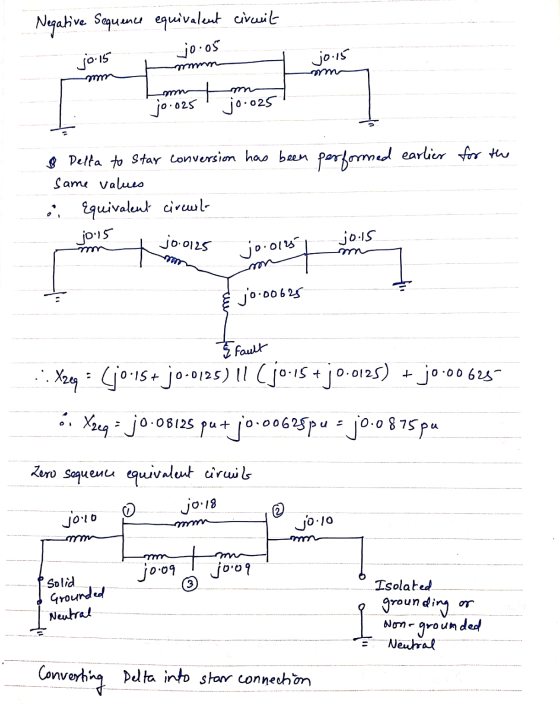
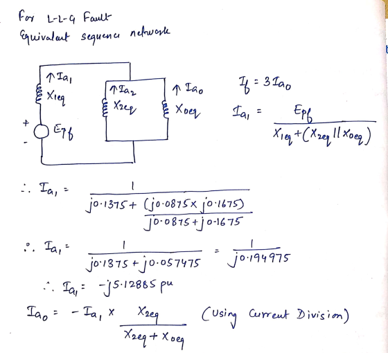
 b) A fault occurs at bus 4 of the network shown in Figure Q3. Pre-fault nodal voltages throughout the network are of 1 +j0 p.u. and the impedance of the electric arc is neglected (Zf-0+)0p.u). The positive, negative and zero sequence impedance parameters of the generator, transmission lines and transformer are given in Figure Q3 x,(1) 30. 15 p.u. 1岚12,-j0.15 p.u. 2 T2)0.15 Figure Q3. Circuit for problem 3b) (i) Assuming a balanced excitation, draw the positive, negative and zero...
Exercise 3 Consider a 2 generator 4 bus power system shown in Figure E3. The impedance data of the network in p.u. are given in Figure E3. A bolted symmetrical three phase fault occurs at bus 4. Assu...
 Exercise 3 Consider a 2 generator 4 bus power system shown in Figure E3. The impedance data of the network in p.u. are given in Figure E3. A bolted symmetrical three phase fault occurs at bus 4. Assuming the prefault bus voltages as I p.u., calculate the fault current and the current delivered by the generators during the fault and the bus voltages during the fault. j0.12 0.05 0.16 j0.18 j0.12 0.15 0.05 j0.12 j0.1 j0.14 4 (2 Figure E3:...
Al power system is shown in the diagram below. A phase A-C fault occurs just before the A radi tr...
 al power system is shown in the diagram below. A phase A-C fault occurs just before the A radi transmission line. Calculate the per-unit fault c pu. urrent in phases A and C. The fault impedance is O.001 Yg Ye TLine Load 0.1j 11kv/66kv x(+)-0.04j x()-0.04i 11 kv Kg(-)-005i Use Sbase 10 MVA. All impedances are given in pu and on 10 MVA base.
al power system is shown in the diagram below. A phase A-C fault occurs just before...
al power system is shown in the diagram below. A phase A-C fault occurs just before the A radi transmission line. Calculate the per-unit fault c pu. urrent in phases A and C. The fault impedance is O.001 Yg Ye TLine Load 0.1j 11kv/66kv x(+)-0.04j x()-0.04i 11 kv Kg(-)-005i Use Sbase 10 MVA. All impedances are given in pu and on 10 MVA base.
al power system is shown in the diagram below. A phase A-C fault occurs just before...
Bus A Bus B R1 TI ine 1 20% 80% line 2 T2 R2 110 kV 11 kV The fault is located at point F, which ...
 Bus A Bus B R1 TI ine 1 20% 80% line 2 T2 R2 110 kV 11 kV The fault is located at point F, which is 20% of the total line 2 length from Bus B Fault MVA 1524.20471 Three-phase fault level in MVA at bus A SPFL (kA) 8 MVA1 MVA2 X1 (96 X2 (96) R1 (2) R2 (Q) z' (Q) Zo (2) Rf (Q) Single phase to ground fault level (kA) at bus A Transformer 1 MVA...
The zero-, positive-, and negative-sequence bus impedance matrices for a three bus power system are given...
 The zero-, positive-, and negative-sequence bus impedance matrices for a three bus power system are given below 5. T0.10 0.15 0.121 Bu0.15 0.10 0.08 pu [0.16 0.10 0.15] Lo.15 0.14 0.30 0.12 0.08 0.35 ZBus ZBus0.10 0.20 0.14 pu Determine the per unit fault current and the bus voltages during fault for (a) A bolted three-phase fault at bus 2. (b) A bolted single line-to-ground fault at bus 2. (c) A bolted line-to-line fault at bus 2 (d) A bolted...
Consider the 3-bus power system single diagram below. A bolted three phase fault occurs at bus...
 Consider the 3-bus power system single diagram below. A bolted three phase fault occurs at bus 3. Using bus impedance matrix calculate the following: 1 j0,2 j0,5 0,3 A2 2 3 A3 j0,3 0,6 j0,2 1.1 1.2 1.3 Fault current Bus voltages Line currents during the fault.
PLEASE SOLVE THIS POWER / LOAD FLOW 07-Elec-B December 2016 Page 7 of 7 Problem 7...
 PLEASE SOLVE THIS POWER / LOAD FLOW
07-Elec-B December 2016 Page 7 of 7 Problem 7 Consider the system shown in the single-line diagram of Figure (5). Here, a 60-Hz synchronous generator having a transient reactance of 0.15 pu. is connected to an infinite bus through a transformer whose reactance is 0.1 p. u. and a double circuit transmission line with circuits having a reactance of 0.6 p.u each as indicated in the figurc. The generator delivers a real power...
PLEASE SOLVE THIS POWER / LOAD FLOW
07-Elec-B December 2016 Page 7 of 7 Problem 7 Consider the system shown in the single-line diagram of Figure (5). Here, a 60-Hz synchronous generator having a transient reactance of 0.15 pu. is connected to an infinite bus through a transformer whose reactance is 0.1 p. u. and a double circuit transmission line with circuits having a reactance of 0.6 p.u each as indicated in the figurc. The generator delivers a real power...
For the system below compute the fault current and the branch contributions for a three phase...
 For the system below compute the fault current and the
branch contributions for a three phase fault.
consider the unloaded system with a pre-fault voltage
of 1.1 pu.
Compute the fault current and the total current of
each branch. Show all calculations and tabulate the final
result.
For the system below compute the fault current and the branch contributions for a three-phase fault. Considerthe unloaded system with a pre-fault voltage 1.1 pu. Compute the fault current and the total current...
For the system below compute the fault current and the
branch contributions for a three phase fault.
consider the unloaded system with a pre-fault voltage
of 1.1 pu.
Compute the fault current and the total current of
each branch. Show all calculations and tabulate the final
result.
For the system below compute the fault current and the branch contributions for a three-phase fault. Considerthe unloaded system with a pre-fault voltage 1.1 pu. Compute the fault current and the total current...
Single line to ground fault analysis Example 9.4 Problem 1 A three-phase, il kV, 30 MVA alternato...
 I need help in matlab codes please
Single line to ground fault analysis Example 9.4 Problem 1 A three-phase, il kV, 30 MVA alternator with grounded neutral has a direct axis subtransien pu respectively based on system base. A single line to ground fault has occurred in phase a. Determine the fault current, line to ground voltages in pu. t, negative sequence and zero sequence reactances of 0.2 pu, 0.3 pu and 0.1 Solution: Phase voltage E.0 pu From equation...
I need help in matlab codes please
Single line to ground fault analysis Example 9.4 Problem 1 A three-phase, il kV, 30 MVA alternator with grounded neutral has a direct axis subtransien pu respectively based on system base. A single line to ground fault has occurred in phase a. Determine the fault current, line to ground voltages in pu. t, negative sequence and zero sequence reactances of 0.2 pu, 0.3 pu and 0.1 Solution: Phase voltage E.0 pu From equation...
 A single line diagram of a power system is shown in Fig. 2. The system data with equipment ratings and assumed sequence reactances are given the following table. The neutrals of the generator and A-Y transformers are solidly grounded. The motor neutral is grounded through a reactance Xn 0.05 per unit on the motor base. Assume that Pre-fault voltage is takin as VF-1.0 ,0° per unit and Pre- fault load current and Δ-Y transformer phase shift are neglected In the...
 b) A fault occurs at bus 4 of the network shown in Figure Q3. Pre-fault nodal voltages throughout the network are of 1 +j0 p.u. and the impedance of the electric arc is neglected (Zf-0+)0p.u). The positive, negative and zero sequence impedance parameters of the generator, transmission lines and transformer are given in Figure Q3 x,(1) 30. 15 p.u. 1岚12,-j0.15 p.u. 2 T2)0.15 Figure Q3. Circuit for problem 3b) (i) Assuming a balanced excitation, draw the positive, negative and zero...
 Exercise 3 Consider a 2 generator 4 bus power system shown in Figure E3. The impedance data of the network in p.u. are given in Figure E3. A bolted symmetrical three phase fault occurs at bus 4. Assuming the prefault bus voltages as I p.u., calculate the fault current and the current delivered by the generators during the fault and the bus voltages during the fault. j0.12 0.05 0.16 j0.18 j0.12 0.15 0.05 j0.12 j0.1 j0.14 4 (2 Figure E3:...
 al power system is shown in the diagram below. A phase A-C fault occurs just before the A radi transmission line. Calculate the per-unit fault c pu. urrent in phases A and C. The fault impedance is O.001 Yg Ye TLine Load 0.1j 11kv/66kv x(+)-0.04j x()-0.04i 11 kv Kg(-)-005i Use Sbase 10 MVA. All impedances are given in pu and on 10 MVA base.
al power system is shown in the diagram below. A phase A-C fault occurs just before...
al power system is shown in the diagram below. A phase A-C fault occurs just before the A radi transmission line. Calculate the per-unit fault c pu. urrent in phases A and C. The fault impedance is O.001 Yg Ye TLine Load 0.1j 11kv/66kv x(+)-0.04j x()-0.04i 11 kv Kg(-)-005i Use Sbase 10 MVA. All impedances are given in pu and on 10 MVA base.
al power system is shown in the diagram below. A phase A-C fault occurs just before...
 Bus A Bus B R1 TI ine 1 20% 80% line 2 T2 R2 110 kV 11 kV The fault is located at point F, which is 20% of the total line 2 length from Bus B Fault MVA 1524.20471 Three-phase fault level in MVA at bus A SPFL (kA) 8 MVA1 MVA2 X1 (96 X2 (96) R1 (2) R2 (Q) z' (Q) Zo (2) Rf (Q) Single phase to ground fault level (kA) at bus A Transformer 1 MVA...
 The zero-, positive-, and negative-sequence bus impedance matrices for a three bus power system are given below 5. T0.10 0.15 0.121 Bu0.15 0.10 0.08 pu [0.16 0.10 0.15] Lo.15 0.14 0.30 0.12 0.08 0.35 ZBus ZBus0.10 0.20 0.14 pu Determine the per unit fault current and the bus voltages during fault for (a) A bolted three-phase fault at bus 2. (b) A bolted single line-to-ground fault at bus 2. (c) A bolted line-to-line fault at bus 2 (d) A bolted...
 Consider the 3-bus power system single diagram below. A bolted three phase fault occurs at bus 3. Using bus impedance matrix calculate the following: 1 j0,2 j0,5 0,3 A2 2 3 A3 j0,3 0,6 j0,2 1.1 1.2 1.3 Fault current Bus voltages Line currents during the fault.
 PLEASE SOLVE THIS POWER / LOAD FLOW
07-Elec-B December 2016 Page 7 of 7 Problem 7 Consider the system shown in the single-line diagram of Figure (5). Here, a 60-Hz synchronous generator having a transient reactance of 0.15 pu. is connected to an infinite bus through a transformer whose reactance is 0.1 p. u. and a double circuit transmission line with circuits having a reactance of 0.6 p.u each as indicated in the figurc. The generator delivers a real power...
PLEASE SOLVE THIS POWER / LOAD FLOW
07-Elec-B December 2016 Page 7 of 7 Problem 7 Consider the system shown in the single-line diagram of Figure (5). Here, a 60-Hz synchronous generator having a transient reactance of 0.15 pu. is connected to an infinite bus through a transformer whose reactance is 0.1 p. u. and a double circuit transmission line with circuits having a reactance of 0.6 p.u each as indicated in the figurc. The generator delivers a real power...
 For the system below compute the fault current and the
branch contributions for a three phase fault.
consider the unloaded system with a pre-fault voltage
of 1.1 pu.
Compute the fault current and the total current of
each branch. Show all calculations and tabulate the final
result.
For the system below compute the fault current and the branch contributions for a three-phase fault. Considerthe unloaded system with a pre-fault voltage 1.1 pu. Compute the fault current and the total current...
For the system below compute the fault current and the
branch contributions for a three phase fault.
consider the unloaded system with a pre-fault voltage
of 1.1 pu.
Compute the fault current and the total current of
each branch. Show all calculations and tabulate the final
result.
For the system below compute the fault current and the branch contributions for a three-phase fault. Considerthe unloaded system with a pre-fault voltage 1.1 pu. Compute the fault current and the total current...
 I need help in matlab codes please
Single line to ground fault analysis Example 9.4 Problem 1 A three-phase, il kV, 30 MVA alternator with grounded neutral has a direct axis subtransien pu respectively based on system base. A single line to ground fault has occurred in phase a. Determine the fault current, line to ground voltages in pu. t, negative sequence and zero sequence reactances of 0.2 pu, 0.3 pu and 0.1 Solution: Phase voltage E.0 pu From equation...
I need help in matlab codes please
Single line to ground fault analysis Example 9.4 Problem 1 A three-phase, il kV, 30 MVA alternator with grounded neutral has a direct axis subtransien pu respectively based on system base. A single line to ground fault has occurred in phase a. Determine the fault current, line to ground voltages in pu. t, negative sequence and zero sequence reactances of 0.2 pu, 0.3 pu and 0.1 Solution: Phase voltage E.0 pu From equation...
Most questions answered within 3 hours.
-
An MNE is this kind of industry when competition in one country
is essentially independent of...
asked 1 hour ago -
. For this set of questions, determine what
proportion of a normal distribution is located betweeneach...
asked 1 hour ago -
A college student is employed as a door-to-door newspaper
salesman. Historical data suggests that the student...
asked 2 hours ago -
MATLAB HW 11 problem using Switch Case and Input commands
Write a script file that calculates...
asked 2 hours ago -
Considering gravitational time dilation, calculate the time that
passes in Earth’s surface while 1 hour passes...
asked 3 hours ago -
Minitab Problem: Take the Lake Hume June rainfall data and find
use the processes outlined in...
asked 4 hours ago -
X Company is trying to decide whether to continue using old
equipment to make Product A...
asked 4 hours ago -
IN PYTHON ONLY !! Program 2: Re-work
program #5 (WeeklyHours) from the previous assignment such that...
asked 4 hours ago -
The average length of time between arrivals at a turnpike
toll-booth is 26 seconds. What is...
asked 6 hours ago -
(a) A piston at 6.1 atm contains a gas that occupies a volume of
3.5 L....
asked 7 hours ago -
Please answer true or false. Words
cannot be changed or added in to make it true...
asked 7 hours ago -
An empty test tube weighs 15.923 grams. Then,
MgCl2•6H2O is added into the test tube. After...
asked 7 hours ago