
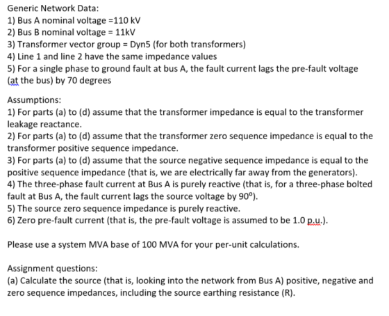
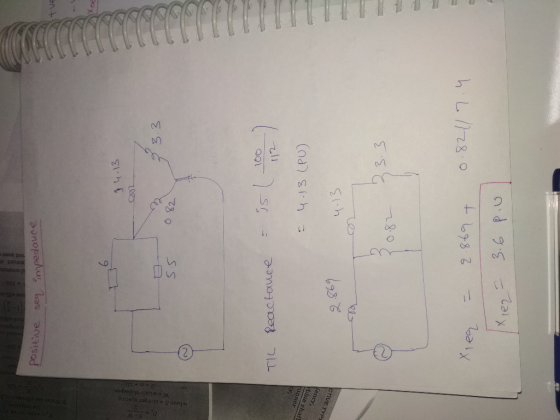
Generic Network Data: 1) Bus A nominal voltage -110 kV 2) Bus B nominal voltage 11kV 3) Transformer vector group Dyn5 (for both transformers) 4) Line 1 and line 2 have the same impedance values 5) For a single phase to ground fault at bus A, the fault current lags the pre-fault voltage (at the bus) by 70 degrees Assumptions: 1) For parts (a) to (d) assume that the transformer impedance is equal to the transformer leakage reactance. 2) For parts (a) to (d) assume that the transformer zero sequence impedance is equal to the transformer positive sequence impedance. 3) For parts (a) to (d) assume that the source negative sequence impedance is equal to the positive sequence impedance (that is, we are electrically far away from the generators). 4) The three-phase fault current at Bus A is purely reactive (that is, for a three-phase bolted fault at Bus A, the fault current lags the source voltage by 90°). 5) The source zero sequence impedance is purely reactive. 6) Zero pre-fault current (that is, the pre-fault voltage is assumed to be 1.0 pu). Please use a system MVA base of 100 MVA for your per-unit calculations Assignment questions: (a) Calculate the source (that is, looking into the network from Bus A) positive, negative and zero sequence impedances, including the source earthing resistance (R)
Homework Answers

Add Answer to:
Bus A Bus B R1 TI ine 1 20% 80% line 2 T2 R2 110 kV 11 kV The fault is located at point F, which ...
Bus A Bus B R1 TI ine 1 20% 80% line 2 T2 R2 110 kV 11 kV The fault is located at point F, which ...
 Bus A Bus B R1 TI ine 1 20% 80% line 2 T2 R2 110 kV 11 kV The fault is located at point F, which is 20% of the total line 2 length from Bus B Fault MVA 1524.20471 Three-phase fault level in MVA at bus A SPFL (kA) 8 MVA1 MVA2 X1 (96 X2 (96) R1 (2) R2 (Q) z' (Q) Zo (2) Rf (Q) Single phase to ground fault level (kA) at bus A Transformer 1 MVA...
Bus A Bus B R1 T1 line 1 20% 80% line 2 T2 R2 110 kV 11 kV The fault is located at point F, which...
 Bus A Bus B R1 T1 line 1 20% 80% line 2 T2 R2 110 kV 11 kV The fault is located at point F, which is 20% of the total line 2 length from Bus B Fault MVA 1524.20471 Three-phase fault level in MVA at bus A SPFL (kA) 8 MVA1 MVA2 X1 (96) X2 (96) R1 (2) R2 (Q) z' (Q) Zo (2) Rf (Q) Single phase to ground fault level (kA) at bus A Transformer 1 MVA...
Bus A Bus B R1 T1 line 1 20% 80% line 2 T2 R2 110 kV 11 kV Note TX impedance TX leakage reactance...
 Bus A Bus B R1 T1 line 1 20% 80% line 2 T2 R2 110 kV 11 kV Note TX impedance TX leakage reactance TX zero sequence impedance-TX positive Data 3 phase fault MVA Bus A 1152 MVA Single P-G level Bus A 8k T1 = T2 = 50MVA X1 0.006 RAk TX1 X2 0.0055 Rik TX2 Earthing resistance-R1-R2-2 ohm z+ sequence reactance 55j) ohm for both sequence impedance Source negative impedance -positive sequence impedance Source zero sequence impedance- purely...
A single line diagram of a power system is shown in Fig. 2. The system data with equipment ratings and assumed sequence reactances are given the following table. The neutrals of the generator and A-Y...
 A single line diagram of a power system is shown in Fig. 2. The system data with equipment ratings and assumed sequence reactances are given the following table. The neutrals of the generator and A-Y transformers are solidly grounded. The motor neutral is grounded through a reactance Xn 0.05 per unit on the motor base. Assume that Pre-fault voltage is takin as VF-1.0 ,0° per unit and Pre- fault load current and Δ-Y transformer phase shift are neglected In the...
a five bus system
 The equipment ratings for a five bus system are given as Generator G1: 50 MVA, 12 kV, Xd
’’=X2=0.20, X0= 0.10 per unit Generator G2: 100 MVA, 15 kV, Xd
’’=0.2, X2=0.23, X0= 0.10 per unit Transformer T1: 50 MVA, 10 kV (Y)/138 kV (Y), X=0.10 per unit Transformer T1: 100 MVA, 15 kV (∆)/138 kV (Y), X=0.10 per unit Each 138 kV line: X1=40 Ohms, X0=100 ohms (1) Draw out the zero-, positive-, and negative- sequence reactance diagrams for the original system
using a 100-MVA,...
The equipment ratings for a five bus system are given as Generator G1: 50 MVA, 12 kV, Xd
’’=X2=0.20, X0= 0.10 per unit Generator G2: 100 MVA, 15 kV, Xd
’’=0.2, X2=0.23, X0= 0.10 per unit Transformer T1: 50 MVA, 10 kV (Y)/138 kV (Y), X=0.10 per unit Transformer T1: 100 MVA, 15 kV (∆)/138 kV (Y), X=0.10 per unit Each 138 kV line: X1=40 Ohms, X0=100 ohms (1) Draw out the zero-, positive-, and negative- sequence reactance diagrams for the original system
using a 100-MVA,...
Transformer TI : 50 MVA, 10 kV Y/138 kV Y, X=0.10 per unit; Transformer T2: 100 MVA, 15 kV D/138 kV Y, X-0.10 per unit; Each 138-kV line: X1-400 A three-phase short circuit occurs at bus 5,...
 Transformer TI : 50 MVA, 10 kV Y/138 kV Y, X=0.10 per unit; Transformer T2: 100 MVA, 15 kV D/138 kV Y, X-0.10 per unit; Each 138-kV line: X1-400 A three-phase short circuit occurs at bus 5, where the prefault voltage is 15 kV. Prefault load current is neglected. (a)Draw the positive-sequence reactance diagram in per-unit on a 100-MVA, 15-kV base in the zone of generator G2. Determine: (b) the The'venin equivalent at the fault, (c) the subtransient fault current...
b) A fault occurs at bus 4 of the network shown in Figure Q3. Pre-fault nodal...
 b) A fault occurs at bus 4 of the network shown in Figure Q3. Pre-fault nodal voltages throughout the network are of 1 +j0 p.u. and the impedance of the electric arc is neglected (Zf-0+)0p.u). The positive, negative and zero sequence impedance parameters of the generator, transmission lines and transformer are given in Figure Q3 x,(1) 30. 15 p.u. 1岚12,-j0.15 p.u. 2 T2)0.15 Figure Q3. Circuit for problem 3b) (i) Assuming a balanced excitation, draw the positive, negative and zero...
2. A single-line diagram of the power system considered is shown in Figure P2a, where negative-...
 2. A single-line diagram of the power system considered is shown in Figure P2a, where negative- and zero-sequence reactances are also given. The neutrals of the generator and A-Y transformers are solidly grounded. The motor neutral is grounded through a reactance Xn = 0.05 per unit on the motor base. The per-unit zero-, positive and negative-sequence networks on a 100-MVA is shown in Figure P26, 13.8-kV base in the zone of the generator. a. Reduce the sequence networks to their...
Assuming there is a FAULT at BUS 3, Determine the thevenin equivalent of each series network...
 Assuming there is a FAULT at BUS 3, Determine the thevenin
equivalent of each series network as viewed from the fault bus.
Given:
-Prefault voltage is 1.0 per unit
-Prefault load currents and delta-wye transformer phase shifts
are neglected
Synchronous generators G1 1000 MVA 15 kVX"-X2 0.18, Xo 0.07 per unit G2 1000 MVA 15 kV X: X, = 0.20, X,-0.10 per unit G3 500 MVA 13.8 kV X: X,-0.15, X,-0.05 per unit G4 750 MVA 13.8 kV X,-0.30, X,-0.40,...
Assuming there is a FAULT at BUS 3, Determine the thevenin
equivalent of each series network as viewed from the fault bus.
Given:
-Prefault voltage is 1.0 per unit
-Prefault load currents and delta-wye transformer phase shifts
are neglected
Synchronous generators G1 1000 MVA 15 kVX"-X2 0.18, Xo 0.07 per unit G2 1000 MVA 15 kV X: X, = 0.20, X,-0.10 per unit G3 500 MVA 13.8 kV X: X,-0.15, X,-0.05 per unit G4 750 MVA 13.8 kV X,-0.30, X,-0.40,...
Single line to ground fault analysis Example 9.4 Problem 1 A three-phase, il kV, 30 MVA alternato...
 I need help in matlab codes please
Single line to ground fault analysis Example 9.4 Problem 1 A three-phase, il kV, 30 MVA alternator with grounded neutral has a direct axis subtransien pu respectively based on system base. A single line to ground fault has occurred in phase a. Determine the fault current, line to ground voltages in pu. t, negative sequence and zero sequence reactances of 0.2 pu, 0.3 pu and 0.1 Solution: Phase voltage E.0 pu From equation...
I need help in matlab codes please
Single line to ground fault analysis Example 9.4 Problem 1 A three-phase, il kV, 30 MVA alternator with grounded neutral has a direct axis subtransien pu respectively based on system base. A single line to ground fault has occurred in phase a. Determine the fault current, line to ground voltages in pu. t, negative sequence and zero sequence reactances of 0.2 pu, 0.3 pu and 0.1 Solution: Phase voltage E.0 pu From equation...
 Bus A Bus B R1 TI ine 1 20% 80% line 2 T2 R2 110 kV 11 kV The fault is located at point F, which is 20% of the total line 2 length from Bus B Fault MVA 1524.20471 Three-phase fault level in MVA at bus A SPFL (kA) 8 MVA1 MVA2 X1 (96 X2 (96) R1 (2) R2 (Q) z' (Q) Zo (2) Rf (Q) Single phase to ground fault level (kA) at bus A Transformer 1 MVA...
 Bus A Bus B R1 T1 line 1 20% 80% line 2 T2 R2 110 kV 11 kV The fault is located at point F, which is 20% of the total line 2 length from Bus B Fault MVA 1524.20471 Three-phase fault level in MVA at bus A SPFL (kA) 8 MVA1 MVA2 X1 (96) X2 (96) R1 (2) R2 (Q) z' (Q) Zo (2) Rf (Q) Single phase to ground fault level (kA) at bus A Transformer 1 MVA...
 Bus A Bus B R1 T1 line 1 20% 80% line 2 T2 R2 110 kV 11 kV Note TX impedance TX leakage reactance TX zero sequence impedance-TX positive Data 3 phase fault MVA Bus A 1152 MVA Single P-G level Bus A 8k T1 = T2 = 50MVA X1 0.006 RAk TX1 X2 0.0055 Rik TX2 Earthing resistance-R1-R2-2 ohm z+ sequence reactance 55j) ohm for both sequence impedance Source negative impedance -positive sequence impedance Source zero sequence impedance- purely...
 A single line diagram of a power system is shown in Fig. 2. The system data with equipment ratings and assumed sequence reactances are given the following table. The neutrals of the generator and A-Y transformers are solidly grounded. The motor neutral is grounded through a reactance Xn 0.05 per unit on the motor base. Assume that Pre-fault voltage is takin as VF-1.0 ,0° per unit and Pre- fault load current and Δ-Y transformer phase shift are neglected In the...
 Transformer TI : 50 MVA, 10 kV Y/138 kV Y, X=0.10 per unit; Transformer T2: 100 MVA, 15 kV D/138 kV Y, X-0.10 per unit; Each 138-kV line: X1-400 A three-phase short circuit occurs at bus 5, where the prefault voltage is 15 kV. Prefault load current is neglected. (a)Draw the positive-sequence reactance diagram in per-unit on a 100-MVA, 15-kV base in the zone of generator G2. Determine: (b) the The'venin equivalent at the fault, (c) the subtransient fault current...
 b) A fault occurs at bus 4 of the network shown in Figure Q3. Pre-fault nodal voltages throughout the network are of 1 +j0 p.u. and the impedance of the electric arc is neglected (Zf-0+)0p.u). The positive, negative and zero sequence impedance parameters of the generator, transmission lines and transformer are given in Figure Q3 x,(1) 30. 15 p.u. 1岚12,-j0.15 p.u. 2 T2)0.15 Figure Q3. Circuit for problem 3b) (i) Assuming a balanced excitation, draw the positive, negative and zero...
 2. A single-line diagram of the power system considered is shown in Figure P2a, where negative- and zero-sequence reactances are also given. The neutrals of the generator and A-Y transformers are solidly grounded. The motor neutral is grounded through a reactance Xn = 0.05 per unit on the motor base. The per-unit zero-, positive and negative-sequence networks on a 100-MVA is shown in Figure P26, 13.8-kV base in the zone of the generator. a. Reduce the sequence networks to their...
 Assuming there is a FAULT at BUS 3, Determine the thevenin
equivalent of each series network as viewed from the fault bus.
Given:
-Prefault voltage is 1.0 per unit
-Prefault load currents and delta-wye transformer phase shifts
are neglected
Synchronous generators G1 1000 MVA 15 kVX"-X2 0.18, Xo 0.07 per unit G2 1000 MVA 15 kV X: X, = 0.20, X,-0.10 per unit G3 500 MVA 13.8 kV X: X,-0.15, X,-0.05 per unit G4 750 MVA 13.8 kV X,-0.30, X,-0.40,...
Assuming there is a FAULT at BUS 3, Determine the thevenin
equivalent of each series network as viewed from the fault bus.
Given:
-Prefault voltage is 1.0 per unit
-Prefault load currents and delta-wye transformer phase shifts
are neglected
Synchronous generators G1 1000 MVA 15 kVX"-X2 0.18, Xo 0.07 per unit G2 1000 MVA 15 kV X: X, = 0.20, X,-0.10 per unit G3 500 MVA 13.8 kV X: X,-0.15, X,-0.05 per unit G4 750 MVA 13.8 kV X,-0.30, X,-0.40,...
 I need help in matlab codes please
Single line to ground fault analysis Example 9.4 Problem 1 A three-phase, il kV, 30 MVA alternator with grounded neutral has a direct axis subtransien pu respectively based on system base. A single line to ground fault has occurred in phase a. Determine the fault current, line to ground voltages in pu. t, negative sequence and zero sequence reactances of 0.2 pu, 0.3 pu and 0.1 Solution: Phase voltage E.0 pu From equation...
I need help in matlab codes please
Single line to ground fault analysis Example 9.4 Problem 1 A three-phase, il kV, 30 MVA alternator with grounded neutral has a direct axis subtransien pu respectively based on system base. A single line to ground fault has occurred in phase a. Determine the fault current, line to ground voltages in pu. t, negative sequence and zero sequence reactances of 0.2 pu, 0.3 pu and 0.1 Solution: Phase voltage E.0 pu From equation...
Most questions answered within 3 hours.
-
A regression equation that describes the relationship between
the amount of the bill ($) at a...
asked 37 minutes ago -
exercise on VSEPR and molecular structrue.
octahedral
SeCl62-
TeCl62-
ClF62-
distorted
SeF62–
IF6–
asked 1 hour ago -
284 mL of a 0.52 M potassium hydroxide solution is added to 467
mL of a...
asked 1 hour ago -
Little’s Law: Val d’Costa is a world famous ski village in the
French Alps. Because of...
asked 1 hour ago -
Find the absolute error D for the calculation if A + B/C=D A=
9.4 +/- 0.4...
asked 2 hours ago -
New Air Heating and Cooling, manufactures furnaces and central
air units. The company pride itself on...
asked 2 hours ago -
A coach uses a new technique to train gymnasts. Seven
gymnasts were randomly selected and their...
asked 4 hours ago -
While rotating the tires on your car you notice a rock [mass =
0.1 Kg] stuck...
asked 6 hours ago -
Using MARS simulator, write MIPS programs according to
the following scenarios: Receive a positive integer number...
asked 8 hours ago -
An object in front of a concave mirror has a real image that is
11.5 cm...
asked 8 hours ago -
Consider the reaction, C3 H8 + O2 --> CO2 + H2O. How many
moles of O2...
asked 10 hours ago -
You and your opponent both roll a fair die. If you both roll the
same number,...
asked 10 hours ago