

fo Figure P4 Problem 5 Equipment ratings for the five-bus power system shown in Figure P5 are as follows: Generator Gl: 50 MVA, 10 kV,x0.2 per unit Generator G2: 100 MVA, 15 kV,xd 0.2 per unit
Homework Answers

Add Answer to:
Transformer TI : 50 MVA, 10 kV Y/138 kV Y, X=0.10 per unit; Transformer T2: 100 MVA, 15 kV D/138 kV Y, X-0.10 per unit; Each 138-kV line: X1-400 A three-phase short circuit occurs at bus 5,...
a five bus system
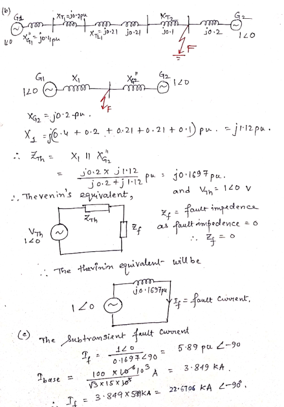
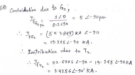
 The equipment ratings for a five bus system are given as Generator G1: 50 MVA, 12 kV, Xd
’’=X2=0.20, X0= 0.10 per unit Generator G2: 100 MVA, 15 kV, Xd
’’=0.2, X2=0.23, X0= 0.10 per unit Transformer T1: 50 MVA, 10 kV (Y)/138 kV (Y), X=0.10 per unit Transformer T1: 100 MVA, 15 kV (∆)/138 kV (Y), X=0.10 per unit Each 138 kV line: X1=40 Ohms, X0=100 ohms (1) Draw out the zero-, positive-, and negative- sequence reactance diagrams for the original system
using a 100-MVA,...
The equipment ratings for a five bus system are given as Generator G1: 50 MVA, 12 kV, Xd
’’=X2=0.20, X0= 0.10 per unit Generator G2: 100 MVA, 15 kV, Xd
’’=0.2, X2=0.23, X0= 0.10 per unit Transformer T1: 50 MVA, 10 kV (Y)/138 kV (Y), X=0.10 per unit Transformer T1: 100 MVA, 15 kV (∆)/138 kV (Y), X=0.10 per unit Each 138 kV line: X1=40 Ohms, X0=100 ohms (1) Draw out the zero-, positive-, and negative- sequence reactance diagrams for the original system
using a 100-MVA,...
Four-bus power system shown in Fig. 1 are as follows: Generator G1: 200 MVA, 7.2 kv,...
 Four-bus power system shown in Fig. 1 are as follows: Generator G1: 200 MVA, 7.2 kv, X -0.15 p.u Generator G2: 250 MVA, 9.6 kV, X-0.12 p.u Generator G3: 500 MVA, 10 kV, X-0.25 p.u Transformer T1:200 MVA, 7.2 Δ /132 Y kV, X= 0.05 p.u Transformer T2: 250 MVA, 9.6 Δ /132 Y kV, X =0.15 p.u Transformer T3: 500 MVA, 10 Δ /132 Y kV, x-0.1 p.u Each 132-kV line:X,-10 Ω 1- A three-phase short circuit occurs at...
Assuming there is a FAULT at BUS 3, Determine the thevenin equivalent of each series network...
 Assuming there is a FAULT at BUS 3, Determine the thevenin
equivalent of each series network as viewed from the fault bus.
Given:
-Prefault voltage is 1.0 per unit
-Prefault load currents and delta-wye transformer phase shifts
are neglected
Synchronous generators G1 1000 MVA 15 kVX"-X2 0.18, Xo 0.07 per unit G2 1000 MVA 15 kV X: X, = 0.20, X,-0.10 per unit G3 500 MVA 13.8 kV X: X,-0.15, X,-0.05 per unit G4 750 MVA 13.8 kV X,-0.30, X,-0.40,...
Assuming there is a FAULT at BUS 3, Determine the thevenin
equivalent of each series network as viewed from the fault bus.
Given:
-Prefault voltage is 1.0 per unit
-Prefault load currents and delta-wye transformer phase shifts
are neglected
Synchronous generators G1 1000 MVA 15 kVX"-X2 0.18, Xo 0.07 per unit G2 1000 MVA 15 kV X: X, = 0.20, X,-0.10 per unit G3 500 MVA 13.8 kV X: X,-0.15, X,-0.05 per unit G4 750 MVA 13.8 kV X,-0.30, X,-0.40,...
The ratings of the components shown in the one-line diagram are G1: 25 MVA, 13.8 kV, x-0.15 pu G2:15MVA, 13 kV, x = 0.1 5 pu. TI : 25 MVA, 13.2/69 kV, x-0. I 1 pu T2: 25 MVA, 69/13.2 kV,x-0.220 pu Tr...
 The ratings of the components shown in the one-line diagram are G1: 25 MVA, 13.8 kV, x-0.15 pu G2:15MVA, 13 kV, x = 0.1 5 pu. TI : 25 MVA, 13.2/69 kV, x-0. I 1 pu T2: 25 MVA, 69/13.2 kV,x-0.220 pu Transmission line: j65 ohms/pha bus 2 BE 165Ω ISMVA e ratings of generator 1 as base valu 25MVA 13.8 kV 1 5% 69113.2 kV13kV 1 1% 13.2169k 1 1% 1- Draw the reactance diagram. 2- Find the Y-bus...
2. A three-phase short circuit occurs at the bus 1 for the system shown in figure...
 2. A three-phase short circuit occurs at the bus 1 for the system shown in figure below. Neglecting prefault currents and assuming that the generator is operating at its rated voltage, determine the subtransient fault current using superposition. bus 1 bus 2 j6522 ww m AY 25 MVA 13.8 kV 15% 25 MVA 13.2/69 KV 11% 25 MVA 69/13.2 kV 11% 15 MVA 13 kV 15%
QUESTION 4. A single-line diagram of a power system is shown in Figure Q3 below, where...
 QUESTION 4. A single-line diagram of a power system is shown in Figure Q3 below, where negative and zero-sequence reactances are also given. The neutrals of the generator and A-Y transformers are solidly grounded. The motor neutral is grounded through a reactance X.=0.05 per unit on the motor base. Prefault voltage is VF1.05<Oº per unit whereas prefault load current is zero. Take A-Y transformer phase shifts into consideration. M Line tool X, - X2 - 200 100 MVA X =...
A single line diagram of a power system is shown in Fig. 2. The system data with equipment ratings and assumed sequence reactances are given the following table. The neutrals of the generator and A-Y...
 A single line diagram of a power system is shown in Fig. 2. The system data with equipment ratings and assumed sequence reactances are given the following table. The neutrals of the generator and A-Y transformers are solidly grounded. The motor neutral is grounded through a reactance Xn 0.05 per unit on the motor base. Assume that Pre-fault voltage is takin as VF-1.0 ,0° per unit and Pre- fault load current and Δ-Y transformer phase shift are neglected In the...
2. A single-line diagram of the power system considered is shown in Figure P2a, where negative-...
 2. A single-line diagram of the power system considered is shown in Figure P2a, where negative- and zero-sequence reactances are also given. The neutrals of the generator and A-Y transformers are solidly grounded. The motor neutral is grounded through a reactance Xn = 0.05 per unit on the motor base. The per-unit zero-, positive and negative-sequence networks on a 100-MVA is shown in Figure P26, 13.8-kV base in the zone of the generator. a. Reduce the sequence networks to their...
The following are the answers: Autumn 2013 T1 G1 5 kV 50 MVA 5/20 kV 50...
 The following are the answers:
Autumn 2013 T1 G1 5 kV 50 MVA 5/20 kV 50 MVA 20 kV 50 MVA X 0.1 p.u Figure A13 In the system shown, per-unit series equivalent impedances are shown for each element. Before a balanced 3-phase fault occurs in the location shown, the pre-fault current is at its rated value at 90 % lagging power factor flowing from generator G1 The generator is operating at full voltage. How much current in kA is...
The following are the answers:
Autumn 2013 T1 G1 5 kV 50 MVA 5/20 kV 50 MVA 20 kV 50 MVA X 0.1 p.u Figure A13 In the system shown, per-unit series equivalent impedances are shown for each element. Before a balanced 3-phase fault occurs in the location shown, the pre-fault current is at its rated value at 90 % lagging power factor flowing from generator G1 The generator is operating at full voltage. How much current in kA is...
1. A three-phase synchronous generator connected to a 345-KV transmission line through a transformer as shown...
 1. A three-phase synchronous generator connected to a 345-KV transmission line through a transformer as shown in Figure P1. Parameters of both generator and transformer are given in the figure. Transformer losses and exciting current are neglected. A three-phase short-circuit occurs on the line side of the circuit breaker when the generator is operated at rated terminal voltage and at no-load. The breaker interrupts the fault three cycles after fault inception. Neglect the effect of the transformer on the time...
 Four-bus power system shown in Fig. 1 are as follows: Generator G1: 200 MVA, 7.2 kv, X -0.15 p.u Generator G2: 250 MVA, 9.6 kV, X-0.12 p.u Generator G3: 500 MVA, 10 kV, X-0.25 p.u Transformer T1:200 MVA, 7.2 Δ /132 Y kV, X= 0.05 p.u Transformer T2: 250 MVA, 9.6 Δ /132 Y kV, X =0.15 p.u Transformer T3: 500 MVA, 10 Δ /132 Y kV, x-0.1 p.u Each 132-kV line:X,-10 Ω 1- A three-phase short circuit occurs at...
 Assuming there is a FAULT at BUS 3, Determine the thevenin
equivalent of each series network as viewed from the fault bus.
Given:
-Prefault voltage is 1.0 per unit
-Prefault load currents and delta-wye transformer phase shifts
are neglected
Synchronous generators G1 1000 MVA 15 kVX"-X2 0.18, Xo 0.07 per unit G2 1000 MVA 15 kV X: X, = 0.20, X,-0.10 per unit G3 500 MVA 13.8 kV X: X,-0.15, X,-0.05 per unit G4 750 MVA 13.8 kV X,-0.30, X,-0.40,...
Assuming there is a FAULT at BUS 3, Determine the thevenin
equivalent of each series network as viewed from the fault bus.
Given:
-Prefault voltage is 1.0 per unit
-Prefault load currents and delta-wye transformer phase shifts
are neglected
Synchronous generators G1 1000 MVA 15 kVX"-X2 0.18, Xo 0.07 per unit G2 1000 MVA 15 kV X: X, = 0.20, X,-0.10 per unit G3 500 MVA 13.8 kV X: X,-0.15, X,-0.05 per unit G4 750 MVA 13.8 kV X,-0.30, X,-0.40,...
 The ratings of the components shown in the one-line diagram are G1: 25 MVA, 13.8 kV, x-0.15 pu G2:15MVA, 13 kV, x = 0.1 5 pu. TI : 25 MVA, 13.2/69 kV, x-0. I 1 pu T2: 25 MVA, 69/13.2 kV,x-0.220 pu Transmission line: j65 ohms/pha bus 2 BE 165Ω ISMVA e ratings of generator 1 as base valu 25MVA 13.8 kV 1 5% 69113.2 kV13kV 1 1% 13.2169k 1 1% 1- Draw the reactance diagram. 2- Find the Y-bus...
 2. A three-phase short circuit occurs at the bus 1 for the system shown in figure below. Neglecting prefault currents and assuming that the generator is operating at its rated voltage, determine the subtransient fault current using superposition. bus 1 bus 2 j6522 ww m AY 25 MVA 13.8 kV 15% 25 MVA 13.2/69 KV 11% 25 MVA 69/13.2 kV 11% 15 MVA 13 kV 15%
 QUESTION 4. A single-line diagram of a power system is shown in Figure Q3 below, where negative and zero-sequence reactances are also given. The neutrals of the generator and A-Y transformers are solidly grounded. The motor neutral is grounded through a reactance X.=0.05 per unit on the motor base. Prefault voltage is VF1.05<Oº per unit whereas prefault load current is zero. Take A-Y transformer phase shifts into consideration. M Line tool X, - X2 - 200 100 MVA X =...
 A single line diagram of a power system is shown in Fig. 2. The system data with equipment ratings and assumed sequence reactances are given the following table. The neutrals of the generator and A-Y transformers are solidly grounded. The motor neutral is grounded through a reactance Xn 0.05 per unit on the motor base. Assume that Pre-fault voltage is takin as VF-1.0 ,0° per unit and Pre- fault load current and Δ-Y transformer phase shift are neglected In the...
 2. A single-line diagram of the power system considered is shown in Figure P2a, where negative- and zero-sequence reactances are also given. The neutrals of the generator and A-Y transformers are solidly grounded. The motor neutral is grounded through a reactance Xn = 0.05 per unit on the motor base. The per-unit zero-, positive and negative-sequence networks on a 100-MVA is shown in Figure P26, 13.8-kV base in the zone of the generator. a. Reduce the sequence networks to their...
 The following are the answers:
Autumn 2013 T1 G1 5 kV 50 MVA 5/20 kV 50 MVA 20 kV 50 MVA X 0.1 p.u Figure A13 In the system shown, per-unit series equivalent impedances are shown for each element. Before a balanced 3-phase fault occurs in the location shown, the pre-fault current is at its rated value at 90 % lagging power factor flowing from generator G1 The generator is operating at full voltage. How much current in kA is...
The following are the answers:
Autumn 2013 T1 G1 5 kV 50 MVA 5/20 kV 50 MVA 20 kV 50 MVA X 0.1 p.u Figure A13 In the system shown, per-unit series equivalent impedances are shown for each element. Before a balanced 3-phase fault occurs in the location shown, the pre-fault current is at its rated value at 90 % lagging power factor flowing from generator G1 The generator is operating at full voltage. How much current in kA is...
 1. A three-phase synchronous generator connected to a 345-KV transmission line through a transformer as shown in Figure P1. Parameters of both generator and transformer are given in the figure. Transformer losses and exciting current are neglected. A three-phase short-circuit occurs on the line side of the circuit breaker when the generator is operated at rated terminal voltage and at no-load. The breaker interrupts the fault three cycles after fault inception. Neglect the effect of the transformer on the time...
Most questions answered within 3 hours.
-
A 10,000 uF capacitor is in series with a 1 uH inductor. What is
Zeq of...
asked 3 minutes ago -
Draw the molecular orbital diagram for O2-
(oxygen molecule with a negative charge).
asked 20 minutes ago -
. The theoretical weight percent of carbon in (CH3)3N is:
A. 20.32% B. 81.95% C. 9.97%...
asked 4 minutes ago -
Of all the different weapons discussed in this chapter that make
up CBRNE,
Which group do...
asked 17 minutes ago -
Floating Point Representation
Consider a computer that stores information using 10 bits words.
The first bit...
asked 11 minutes ago -
Given the following JavaScript code, what will be displayed on
the web page?
var x =...
asked 28 minutes ago -
The cynics, skeptics, epicureans, & stoics were most
philosophies that dealt with:
a. the physical...
asked 29 minutes ago -
The hydronium ion concentration of an aqueous solution of 0.333
M trimethylamine (a weak base with...
asked 31 minutes ago -
A buffer is prepared by partially titrating 50.00 mL of 0.964 M
benzoic acid using 0,100...
asked 34 minutes ago -
For a Generalized Additive Model, what does a large
edf(empirical distribution function) value mean?
Thank you...
asked 47 minutes ago -
questions for Biology lab
An agarose gel electrophoresis assay performed with high quality
will NOT have...
asked 51 minutes ago -
A spring with spring constant 400 N/m is anchored at the bottom
of a frictionless 30^∘...
asked 55 minutes ago