
Homework Answers

Add Answer to:
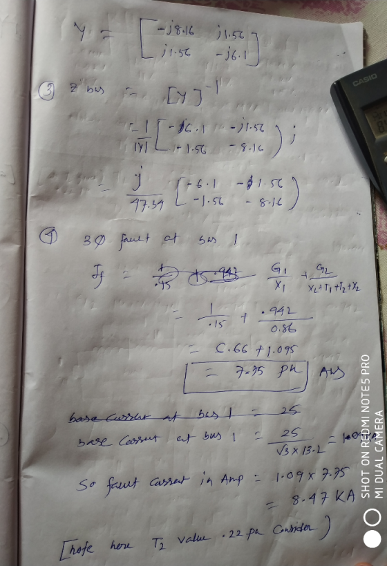
The ratings of the components shown in the one-line diagram are G1: 25 MVA, 13.8 kV, x-0.15 pu G2:15MVA, 13 kV, x = 0.1 5 pu. TI : 25 MVA, 13.2/69 kV, x-0. I 1 pu T2: 25 MVA, 69/13.2 kV,x-0.220 pu Tr...
Transformer TI : 50 MVA, 10 kV Y/138 kV Y, X=0.10 per unit; Transformer T2: 100 MVA, 15 kV D/138 kV Y, X-0.10 per unit; Each 138-kV line: X1-400 A three-phase short circuit occurs at bus 5,...
 Transformer TI : 50 MVA, 10 kV Y/138 kV Y, X=0.10 per unit; Transformer T2: 100 MVA, 15 kV D/138 kV Y, X-0.10 per unit; Each 138-kV line: X1-400 A three-phase short circuit occurs at bus 5, where the prefault voltage is 15 kV. Prefault load current is neglected. (a)Draw the positive-sequence reactance diagram in per-unit on a 100-MVA, 15-kV base in the zone of generator G2. Determine: (b) the The'venin equivalent at the fault, (c) the subtransient fault current...
The single-line diagram of a three-phase power system is shown. Equipment ratings are given as follows
 The single-line diagram of a three-phase power system is shown. Equipment ratings are given as follows: The inductor connected to generator 3 neutral has a reactance of \(0.05\) pu using generator 3 ratings as a base.1. Draw the zero-, positive-, and negative -sequence reactance diagrams using a \(1000 \mathrm{MVA}, 765 \mathrm{kV}\) base in the zone of line \(1-2\).2. Faults at bus 2 are of interest. Determine the Thevenin equivalent of each sequence network as viewed from the fault bus. Prefault voltage...
A single line diagram of a power system is shown in Fig. 2. The system data with equipment ratings and assumed sequence reactances are given the following table. The neutrals of the generator and A-Y...
 A single line diagram of a power system is shown in Fig. 2. The system data with equipment ratings and assumed sequence reactances are given the following table. The neutrals of the generator and A-Y transformers are solidly grounded. The motor neutral is grounded through a reactance Xn 0.05 per unit on the motor base. Assume that Pre-fault voltage is takin as VF-1.0 ,0° per unit and Pre- fault load current and Δ-Y transformer phase shift are neglected In the...
3) The single-line diagram of a three-phase power system is shown in Fig. 1. Equipment ratings...
 3) The single-line diagram of a three-phase power system is shown in Fig. 1. Equipment ratings are given as follows: G1 1,000 MVA, 15.0 kV, 20.18, o 0.07 pu G2 : 1,000 MVA. 15.0 kV, 攻=エ1 =エ2 = 0.20, ro = 0.10 pu G3 : 500 MVA, 13.8 kV. 1" = 띠 z2 = 0.15, zo 0.05 pu G4 : 750 MVA, 13.8 kV. ェd =ェ1 = 0.30, T2 = 0.40 ro = 0.10 pu Ti : 1,000 MVA. 15.0Δ/765Y...
03 Consider the following one line diagram. The generator is rated at 25 MVA, IN has...
 03 Consider the following one line diagram. The generator is rated at 25 MVA, IN has subtransient reactance of 20 %. The transmission line has a reactance of 10 The subtransient reactance of motorlis 0.345 pu where is that ol second more pu. Each motor has the following ratings. 10 MVA and 11 kV. Both transformers are rated at 25 MVA and have a reactance of 8.05% each; the transformers 1 and 2 have voltage ratio of 11/121 KV and...
Consider the single-line diagram of the three-phase power system shown in Figure 1. Component ratings are...
 Consider the single-line diagram of the three-phase power system shown in Figure 1. Component ratings are as follows: Generator G1: 750 MVA, 18 kV, X0.2 per unit Generator G2: 750 MVA, 18 kV, X 0.2 per unit Synchronous Motor M: 1,500 MVA, 20 kV, X-20% A-Y Transformers Ti, T2, T's, & T.: 750 MVA, 500 kV Y/20 kV A, X = 10% Y-Y Transformer T's 1,500 MVA, 500 kV Y/20 kV Y, X-10% ne L:X (a) Using bases of 100...
Problem #1 Part I (50 points) Consider the following one-line diagram of a three-phase power system. Assume that the system has the following base quantities: S3 100 MVA, and VbaselL 38 kV at the...
 Problem #1 Part I (50 points) Consider the following one-line diagram of a three-phase power system. Assume that the system has the following base quantities: S3 100 MVA, and VbaselL 38 kV at the generator side. The rated line-to-line terminal voltage of the generator (BUS 1) is 38 kV. A single-circuit three-phase transposed overhead line composed by one ACSR Partridge conductor per phase with vertical configuration. The transmission line length is 50 km and the distance between phases a-b, b-c...
solve no: 3.14 , 3.16, 3.19 please show each step and solve for beginners 120 Power...
 solve no: 3.14 , 3.16, 3.19
please show each step and solve for beginners
120 Power System Analysis 3.12. A single-phase system similar to that shown in Figure 3.11 has two transformers A-B a B-C connected by a line B feeding a load at the receiving end C. The ratings and parame ter values of the components are 500 V/1.5 kV, 9.6 kVA. leakage reactance 5 % 1.2 kV/120 V, 7.2 kVA, leakage reactance 4 % series impedance (0.5 +...
solve no: 3.14 , 3.16, 3.19
please show each step and solve for beginners
120 Power System Analysis 3.12. A single-phase system similar to that shown in Figure 3.11 has two transformers A-B a B-C connected by a line B feeding a load at the receiving end C. The ratings and parame ter values of the components are 500 V/1.5 kV, 9.6 kVA. leakage reactance 5 % 1.2 kV/120 V, 7.2 kVA, leakage reactance 4 % series impedance (0.5 +...
 Transformer TI : 50 MVA, 10 kV Y/138 kV Y, X=0.10 per unit; Transformer T2: 100 MVA, 15 kV D/138 kV Y, X-0.10 per unit; Each 138-kV line: X1-400 A three-phase short circuit occurs at bus 5, where the prefault voltage is 15 kV. Prefault load current is neglected. (a)Draw the positive-sequence reactance diagram in per-unit on a 100-MVA, 15-kV base in the zone of generator G2. Determine: (b) the The'venin equivalent at the fault, (c) the subtransient fault current...
 The single-line diagram of a three-phase power system is shown. Equipment ratings are given as follows: The inductor connected to generator 3 neutral has a reactance of \(0.05\) pu using generator 3 ratings as a base.1. Draw the zero-, positive-, and negative -sequence reactance diagrams using a \(1000 \mathrm{MVA}, 765 \mathrm{kV}\) base in the zone of line \(1-2\).2. Faults at bus 2 are of interest. Determine the Thevenin equivalent of each sequence network as viewed from the fault bus. Prefault voltage...
 A single line diagram of a power system is shown in Fig. 2. The system data with equipment ratings and assumed sequence reactances are given the following table. The neutrals of the generator and A-Y transformers are solidly grounded. The motor neutral is grounded through a reactance Xn 0.05 per unit on the motor base. Assume that Pre-fault voltage is takin as VF-1.0 ,0° per unit and Pre- fault load current and Δ-Y transformer phase shift are neglected In the...
 3) The single-line diagram of a three-phase power system is shown in Fig. 1. Equipment ratings are given as follows: G1 1,000 MVA, 15.0 kV, 20.18, o 0.07 pu G2 : 1,000 MVA. 15.0 kV, 攻=エ1 =エ2 = 0.20, ro = 0.10 pu G3 : 500 MVA, 13.8 kV. 1" = 띠 z2 = 0.15, zo 0.05 pu G4 : 750 MVA, 13.8 kV. ェd =ェ1 = 0.30, T2 = 0.40 ro = 0.10 pu Ti : 1,000 MVA. 15.0Δ/765Y...
 03 Consider the following one line diagram. The generator is rated at 25 MVA, IN has subtransient reactance of 20 %. The transmission line has a reactance of 10 The subtransient reactance of motorlis 0.345 pu where is that ol second more pu. Each motor has the following ratings. 10 MVA and 11 kV. Both transformers are rated at 25 MVA and have a reactance of 8.05% each; the transformers 1 and 2 have voltage ratio of 11/121 KV and...
 Consider the single-line diagram of the three-phase power system shown in Figure 1. Component ratings are as follows: Generator G1: 750 MVA, 18 kV, X0.2 per unit Generator G2: 750 MVA, 18 kV, X 0.2 per unit Synchronous Motor M: 1,500 MVA, 20 kV, X-20% A-Y Transformers Ti, T2, T's, & T.: 750 MVA, 500 kV Y/20 kV A, X = 10% Y-Y Transformer T's 1,500 MVA, 500 kV Y/20 kV Y, X-10% ne L:X (a) Using bases of 100...
 Problem #1 Part I (50 points) Consider the following one-line diagram of a three-phase power system. Assume that the system has the following base quantities: S3 100 MVA, and VbaselL 38 kV at the generator side. The rated line-to-line terminal voltage of the generator (BUS 1) is 38 kV. A single-circuit three-phase transposed overhead line composed by one ACSR Partridge conductor per phase with vertical configuration. The transmission line length is 50 km and the distance between phases a-b, b-c...
 solve no: 3.14 , 3.16, 3.19
please show each step and solve for beginners
120 Power System Analysis 3.12. A single-phase system similar to that shown in Figure 3.11 has two transformers A-B a B-C connected by a line B feeding a load at the receiving end C. The ratings and parame ter values of the components are 500 V/1.5 kV, 9.6 kVA. leakage reactance 5 % 1.2 kV/120 V, 7.2 kVA, leakage reactance 4 % series impedance (0.5 +...
solve no: 3.14 , 3.16, 3.19
please show each step and solve for beginners
120 Power System Analysis 3.12. A single-phase system similar to that shown in Figure 3.11 has two transformers A-B a B-C connected by a line B feeding a load at the receiving end C. The ratings and parame ter values of the components are 500 V/1.5 kV, 9.6 kVA. leakage reactance 5 % 1.2 kV/120 V, 7.2 kVA, leakage reactance 4 % series impedance (0.5 +...
Most questions answered within 3 hours.
-
In a random sample of 100 homes in a certain city, it is found
that 10...
asked 2 minutes ago -
A compression ignition engine is being analyzed. The
residual gas fraction is xr=0.02. The fuel-to-air
equivalence ratio is...
asked 11 minutes ago -
Which of the following is FALSE about Slow Twitch Fibers (Slow
fibers, slow oxidative fibers) compared...
asked 15 minutes ago -
Need help with drawing the mechanism of succinic anhydride to
succinimide via ammonia and heat. Kind...
asked 35 minutes ago -
Steve is a sales rep for Clearwater Purification Systems, a
national manufacturer of residential water treatment...
asked 19 minutes ago -
Question 4. Using your knowledge of IS-LM, solve the following:
8
12
1+r 1+r
(a) If...
asked 24 minutes ago -
Paige's Properties Inc. reported 2018 net income of $2.90
million and depreciation of $269,000. Paige's Properties,...
asked 33 minutes ago -
Using loops, write a C# program that asks the user to
enter repeatedly an integer number,...
asked 39 minutes ago -
A researcher conducts an experiment comparing three treatment
conditions. The data consist of n = 34...
asked 57 minutes ago -
A generating station is producing 1.8 x 10⁶ W of power that is
to be sent...
asked 48 minutes ago -
Consider the reaction Mg(s)+Fe2+(aq)→Mg2+(aq)+Fe(s) at 49 ∘C ,
where [Fe2+]= 3.30 M and [Mg2+]= 0.210 M...
asked 49 minutes ago -
Of men aged 65 and over 20.5% are still in the US labor force. A
random...
asked 1 hour ago