


Homework Answers

remaining anwers ill write again because time limit has finished. hope you understand.
Add Answer to:
The following are the answers:
Autumn 2013 T1 G1 5 kV 50 MVA 5/20 kV 50...
Four-bus power system shown in Fig. 1 are as follows: Generator G1: 200 MVA, 7.2 kv,...
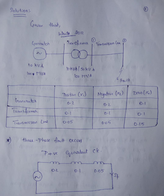
 Four-bus power system shown in Fig. 1 are as follows: Generator G1: 200 MVA, 7.2 kv, X -0.15 p.u Generator G2: 250 MVA, 9.6 kV, X-0.12 p.u Generator G3: 500 MVA, 10 kV, X-0.25 p.u Transformer T1:200 MVA, 7.2 Δ /132 Y kV, X= 0.05 p.u Transformer T2: 250 MVA, 9.6 Δ /132 Y kV, X =0.15 p.u Transformer T3: 500 MVA, 10 Δ /132 Y kV, x-0.1 p.u Each 132-kV line:X,-10 Ω 1- A three-phase short circuit occurs at...
Transformer TI : 50 MVA, 10 kV Y/138 kV Y, X=0.10 per unit; Transformer T2: 100 MVA, 15 kV D/138 kV Y, X-0.10 per unit; Each 138-kV line: X1-400 A three-phase short circuit occurs at bus 5,...
 Transformer TI : 50 MVA, 10 kV Y/138 kV Y, X=0.10 per unit; Transformer T2: 100 MVA, 15 kV D/138 kV Y, X-0.10 per unit; Each 138-kV line: X1-400 A three-phase short circuit occurs at bus 5, where the prefault voltage is 15 kV. Prefault load current is neglected. (a)Draw the positive-sequence reactance diagram in per-unit on a 100-MVA, 15-kV base in the zone of generator G2. Determine: (b) the The'venin equivalent at the fault, (c) the subtransient fault current...
A 50 Hz, 250 MVA synchronous generator having inertia constant H=5 MJ/MVA is connected to an infinite bus through trans...
 A 50 Hz, 250 MVA synchronous generator having inertia constant H=5 MJ/MVA is connected to an infinite bus through transformer and transmission line as shown below. The transformer reactance is based on 500 MVA, while the other impedances are based on the generator MVA Infinite bus 1 2 3 XL 0.1 pu - oto G1 V= 1.0 pu X 0.1 pu Xd = 0.3 pu at 500 MVA The generator is delivering 0.8 of full load current at a power...
Problem 2 (50 points): The synchronous generator shown in the figure below is operated at its rat...
 Problem 2 (50 points): The synchronous generator shown in the figure below is operated at its rated apparent power (100 MVA), 0.95 pf. lagging, and 5% above rated voltage. Determine the subtransient fault current if a three phase short circuit fault occurs at the terminal of the motor (Bus 2) T1 2 100 MVA 100 MVA 13.8 kV 13.8 kV Δ/138 kVY X" = 0.15 X = 0.10 100 MVA 138 kV Y/13.8 kV Δ X0.10 100 MVA 13.8 kV...
3. A 200 MVA, 20 kV, 60 Hz Y-connected solidly grounded three phase synchronous generator connect...
 3. A 200 MVA, 20 kV, 60 Hz Y-connected solidly grounded three phase synchronous generator connected through a 200 MVA 20/138 KV Y-Y transformer to a 138 kV transmission line. The generator reactances to the machine's own base are X-1.10 Both of the transformers Y connections are solidly grounded and its positive, negative and zero sequence series resitances are all 0.10 pu. a. What is the voltage at the terminals of the generator during the sub transient period if a...
4. A generator having a solidly grounded neutral and rated 50-MVA, 30-kV has positive, negative-, and...
 4. A generator having a solidly grounded neutral and rated 50-MVA, 30-kV has positive, negative-, and zero-sequence reactances of 35, 25, and 5 percent, respectively (a) What reactance must be placed in the generator neutral to limit the fault current for a bolted line-to-ground fault to that for a bolted three-phase fault? (b) What reactance must be placed in the generator neutral to limit the fault current for a bolted double line-to-ground fault to that for a bolted three-phase fault?
1. A three-phase synchronous generator connected to a 345-KV transmission line through a transformer as shown...
 1. A three-phase synchronous generator connected to a 345-KV transmission line through a transformer as shown in Figure P1. Parameters of both generator and transformer are given in the figure. Transformer losses and exciting current are neglected. A three-phase short-circuit occurs on the line side of the circuit breaker when the generator is operated at rated terminal voltage and at no-load. The breaker interrupts the fault three cycles after fault inception. Neglect the effect of the transformer on the time...
The ratings of the components shown in the one-line diagram are G1: 25 MVA, 13.8 kV, x-0.15 pu G2:15MVA, 13 kV, x = 0.1 5 pu. TI : 25 MVA, 13.2/69 kV, x-0. I 1 pu T2: 25 MVA, 69/13.2 kV,x-0.220 pu Tr...
 The ratings of the components shown in the one-line diagram are G1: 25 MVA, 13.8 kV, x-0.15 pu G2:15MVA, 13 kV, x = 0.1 5 pu. TI : 25 MVA, 13.2/69 kV, x-0. I 1 pu T2: 25 MVA, 69/13.2 kV,x-0.220 pu Transmission line: j65 ohms/pha bus 2 BE 165Ω ISMVA e ratings of generator 1 as base valu 25MVA 13.8 kV 1 5% 69113.2 kV13kV 1 1% 13.2169k 1 1% 1- Draw the reactance diagram. 2- Find the Y-bus...
2. nBase MVA 100p LI Base KV G1 20kV Base KV Lines 220kv G13 phase 20...
 2. nBase MVA 100p LI Base KV G1 20kV Base KV Lines 220kv G13 phase 20 kv, 100 MVA Xd-1, Xd-0.3, Xd"-0.2, Xo-0.8 H-1s T1 3 phase 100 MVA20kv -220kv, DY,X-0.1 L1, L2 Ro X1-0.2 pu on given base Y ignored L2 The infinite bus voltage is 1 PU The generator supplies 0.6 pu real power at 0.8 pf lagging to the infinite bus a. Sketch an impedance diagram appropriate for transient stability analysis b. Calculate the internal transient voltage...
Bus A Bus B R1 T1 line 1 20% 80% line 2 T2 R2 110 kV 11 kV The fault is located at point F, which...
 Bus A Bus B R1 T1 line 1 20% 80% line 2 T2 R2 110 kV 11 kV The fault is located at point F, which is 20% of the total line 2 length from Bus B Fault MVA 1524.20471 Three-phase fault level in MVA at bus A SPFL (kA) 8 MVA1 MVA2 X1 (96) X2 (96) R1 (2) R2 (Q) z' (Q) Zo (2) Rf (Q) Single phase to ground fault level (kA) at bus A Transformer 1 MVA...
 Four-bus power system shown in Fig. 1 are as follows: Generator G1: 200 MVA, 7.2 kv, X -0.15 p.u Generator G2: 250 MVA, 9.6 kV, X-0.12 p.u Generator G3: 500 MVA, 10 kV, X-0.25 p.u Transformer T1:200 MVA, 7.2 Δ /132 Y kV, X= 0.05 p.u Transformer T2: 250 MVA, 9.6 Δ /132 Y kV, X =0.15 p.u Transformer T3: 500 MVA, 10 Δ /132 Y kV, x-0.1 p.u Each 132-kV line:X,-10 Ω 1- A three-phase short circuit occurs at...
 Transformer TI : 50 MVA, 10 kV Y/138 kV Y, X=0.10 per unit; Transformer T2: 100 MVA, 15 kV D/138 kV Y, X-0.10 per unit; Each 138-kV line: X1-400 A three-phase short circuit occurs at bus 5, where the prefault voltage is 15 kV. Prefault load current is neglected. (a)Draw the positive-sequence reactance diagram in per-unit on a 100-MVA, 15-kV base in the zone of generator G2. Determine: (b) the The'venin equivalent at the fault, (c) the subtransient fault current...
 A 50 Hz, 250 MVA synchronous generator having inertia constant H=5 MJ/MVA is connected to an infinite bus through transformer and transmission line as shown below. The transformer reactance is based on 500 MVA, while the other impedances are based on the generator MVA Infinite bus 1 2 3 XL 0.1 pu - oto G1 V= 1.0 pu X 0.1 pu Xd = 0.3 pu at 500 MVA The generator is delivering 0.8 of full load current at a power...
 Problem 2 (50 points): The synchronous generator shown in the figure below is operated at its rated apparent power (100 MVA), 0.95 pf. lagging, and 5% above rated voltage. Determine the subtransient fault current if a three phase short circuit fault occurs at the terminal of the motor (Bus 2) T1 2 100 MVA 100 MVA 13.8 kV 13.8 kV Δ/138 kVY X" = 0.15 X = 0.10 100 MVA 138 kV Y/13.8 kV Δ X0.10 100 MVA 13.8 kV...
 3. A 200 MVA, 20 kV, 60 Hz Y-connected solidly grounded three phase synchronous generator connected through a 200 MVA 20/138 KV Y-Y transformer to a 138 kV transmission line. The generator reactances to the machine's own base are X-1.10 Both of the transformers Y connections are solidly grounded and its positive, negative and zero sequence series resitances are all 0.10 pu. a. What is the voltage at the terminals of the generator during the sub transient period if a...
 4. A generator having a solidly grounded neutral and rated 50-MVA, 30-kV has positive, negative-, and zero-sequence reactances of 35, 25, and 5 percent, respectively (a) What reactance must be placed in the generator neutral to limit the fault current for a bolted line-to-ground fault to that for a bolted three-phase fault? (b) What reactance must be placed in the generator neutral to limit the fault current for a bolted double line-to-ground fault to that for a bolted three-phase fault?
 1. A three-phase synchronous generator connected to a 345-KV transmission line through a transformer as shown in Figure P1. Parameters of both generator and transformer are given in the figure. Transformer losses and exciting current are neglected. A three-phase short-circuit occurs on the line side of the circuit breaker when the generator is operated at rated terminal voltage and at no-load. The breaker interrupts the fault three cycles after fault inception. Neglect the effect of the transformer on the time...
 The ratings of the components shown in the one-line diagram are G1: 25 MVA, 13.8 kV, x-0.15 pu G2:15MVA, 13 kV, x = 0.1 5 pu. TI : 25 MVA, 13.2/69 kV, x-0. I 1 pu T2: 25 MVA, 69/13.2 kV,x-0.220 pu Transmission line: j65 ohms/pha bus 2 BE 165Ω ISMVA e ratings of generator 1 as base valu 25MVA 13.8 kV 1 5% 69113.2 kV13kV 1 1% 13.2169k 1 1% 1- Draw the reactance diagram. 2- Find the Y-bus...
 2. nBase MVA 100p LI Base KV G1 20kV Base KV Lines 220kv G13 phase 20 kv, 100 MVA Xd-1, Xd-0.3, Xd"-0.2, Xo-0.8 H-1s T1 3 phase 100 MVA20kv -220kv, DY,X-0.1 L1, L2 Ro X1-0.2 pu on given base Y ignored L2 The infinite bus voltage is 1 PU The generator supplies 0.6 pu real power at 0.8 pf lagging to the infinite bus a. Sketch an impedance diagram appropriate for transient stability analysis b. Calculate the internal transient voltage...
 Bus A Bus B R1 T1 line 1 20% 80% line 2 T2 R2 110 kV 11 kV The fault is located at point F, which is 20% of the total line 2 length from Bus B Fault MVA 1524.20471 Three-phase fault level in MVA at bus A SPFL (kA) 8 MVA1 MVA2 X1 (96) X2 (96) R1 (2) R2 (Q) z' (Q) Zo (2) Rf (Q) Single phase to ground fault level (kA) at bus A Transformer 1 MVA...
Most questions answered within 3 hours.
-
The English mathematician John Kerrich tossed a coin
10,000 times and obtained 5067 heads.
a. calculate...
asked 9 minutes ago -
13. Use the Student's t-distribution to find the t-value for
each of the given scenarios. Round...
asked 2 minutes ago -
Explain the nutrition assessment for the lower gastrointestinal
tract, including the components of client history, anthropometric...
asked 1 minute ago -
1.Marc has tried to quit heroin seven times only to
relapse each and every time. Marc...
asked 10 minutes ago -
A process has an input as the flow q gal/min, and an
output temperature T Fahrenheit. Initially,...
asked 15 minutes ago -
A sample of 30 patients in a doctor's office showed that they
had to wait an...
asked 21 minutes ago -
Please write 6 to 10 paragraphs on the risks associated with
digging an underground hole.
Write...
asked 27 minutes ago -
The function x = (7.9 m) cos[(4πrad/s)t + π/3 rad] gives the
simple harmonic motion of...
asked 28 minutes ago -
A sample of steam with a mass of 0.501 g at a temperature of 100
∘C...
asked 1 hour ago -
I1(t) and I2(t) describe the intensity of two
light waves.
I1(t)= 10sin(30t+π/4)
I2(t)=
10sin(30.4t+π)
Assume that...
asked 56 minutes ago -
True or False: Spinal nerves emerging from the vertebral column
are ONLY motor OR sensory.
Select...
asked 43 minutes ago -
last question i found wrong so downvoted so dont copy
paste or dont try if you...
asked 39 minutes ago