Assuming there is a FAULT at BUS 3, Determine the thevenin equivalent of each series network as viewed from the fault bus.
Given:
-Prefault voltage is 1.0 per unit
-Prefault load currents and delta-wye transformer phase shifts are neglected
Homework Answers


Add Answer to:
Assuming there is a FAULT at BUS 3, Determine the thevenin
equivalent of each series network...
a five bus system
 The equipment ratings for a five bus system are given as Generator G1: 50 MVA, 12 kV, Xd
’’=X2=0.20, X0= 0.10 per unit Generator G2: 100 MVA, 15 kV, Xd
’’=0.2, X2=0.23, X0= 0.10 per unit Transformer T1: 50 MVA, 10 kV (Y)/138 kV (Y), X=0.10 per unit Transformer T1: 100 MVA, 15 kV (∆)/138 kV (Y), X=0.10 per unit Each 138 kV line: X1=40 Ohms, X0=100 ohms (1) Draw out the zero-, positive-, and negative- sequence reactance diagrams for the original system
using a 100-MVA,...
The equipment ratings for a five bus system are given as Generator G1: 50 MVA, 12 kV, Xd
’’=X2=0.20, X0= 0.10 per unit Generator G2: 100 MVA, 15 kV, Xd
’’=0.2, X2=0.23, X0= 0.10 per unit Transformer T1: 50 MVA, 10 kV (Y)/138 kV (Y), X=0.10 per unit Transformer T1: 100 MVA, 15 kV (∆)/138 kV (Y), X=0.10 per unit Each 138 kV line: X1=40 Ohms, X0=100 ohms (1) Draw out the zero-, positive-, and negative- sequence reactance diagrams for the original system
using a 100-MVA,...
Transformer TI : 50 MVA, 10 kV Y/138 kV Y, X=0.10 per unit; Transformer T2: 100 MVA, 15 kV D/138 kV Y, X-0.10 per unit; Each 138-kV line: X1-400 A three-phase short circuit occurs at bus 5,...
 Transformer TI : 50 MVA, 10 kV Y/138 kV Y, X=0.10 per unit; Transformer T2: 100 MVA, 15 kV D/138 kV Y, X-0.10 per unit; Each 138-kV line: X1-400 A three-phase short circuit occurs at bus 5, where the prefault voltage is 15 kV. Prefault load current is neglected. (a)Draw the positive-sequence reactance diagram in per-unit on a 100-MVA, 15-kV base in the zone of generator G2. Determine: (b) the The'venin equivalent at the fault, (c) the subtransient fault current...
QUESTION 4. A single-line diagram of a power system is shown in Figure Q3 below, where...
 QUESTION 4. A single-line diagram of a power system is shown in Figure Q3 below, where negative and zero-sequence reactances are also given. The neutrals of the generator and A-Y transformers are solidly grounded. The motor neutral is grounded through a reactance X.=0.05 per unit on the motor base. Prefault voltage is VF1.05<Oº per unit whereas prefault load current is zero. Take A-Y transformer phase shifts into consideration. M Line tool X, - X2 - 200 100 MVA X =...
Four-bus power system shown in Fig. 1 are as follows: Generator G1: 200 MVA, 7.2 kv,...
 Four-bus power system shown in Fig. 1 are as follows: Generator G1: 200 MVA, 7.2 kv, X -0.15 p.u Generator G2: 250 MVA, 9.6 kV, X-0.12 p.u Generator G3: 500 MVA, 10 kV, X-0.25 p.u Transformer T1:200 MVA, 7.2 Δ /132 Y kV, X= 0.05 p.u Transformer T2: 250 MVA, 9.6 Δ /132 Y kV, X =0.15 p.u Transformer T3: 500 MVA, 10 Δ /132 Y kV, x-0.1 p.u Each 132-kV line:X,-10 Ω 1- A three-phase short circuit occurs at...
2. A single-line diagram of the power system considered is shown in Figure P2a, where negative-...
 2. A single-line diagram of the power system considered is shown in Figure P2a, where negative- and zero-sequence reactances are also given. The neutrals of the generator and A-Y transformers are solidly grounded. The motor neutral is grounded through a reactance Xn = 0.05 per unit on the motor base. The per-unit zero-, positive and negative-sequence networks on a 100-MVA is shown in Figure P26, 13.8-kV base in the zone of the generator. a. Reduce the sequence networks to their...
3) The single-line diagram of a three-phase power system is shown in Fig. 1. Equipment ratings...
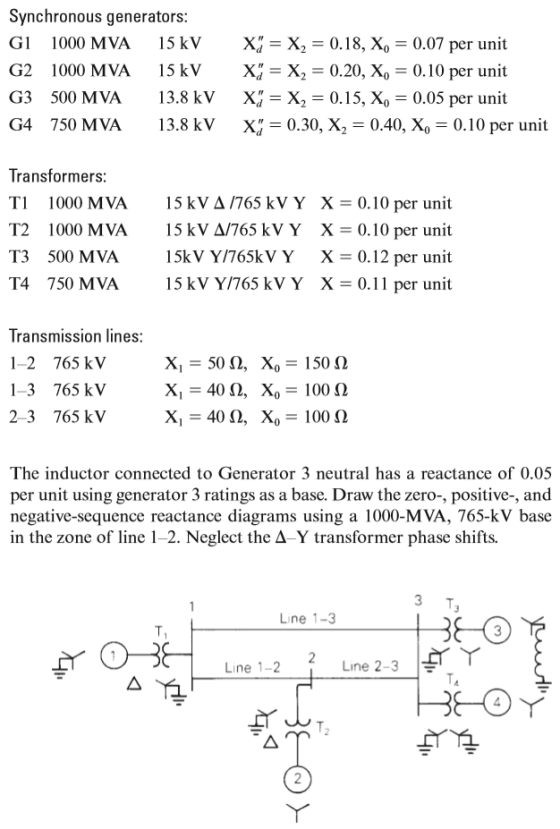
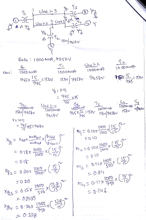
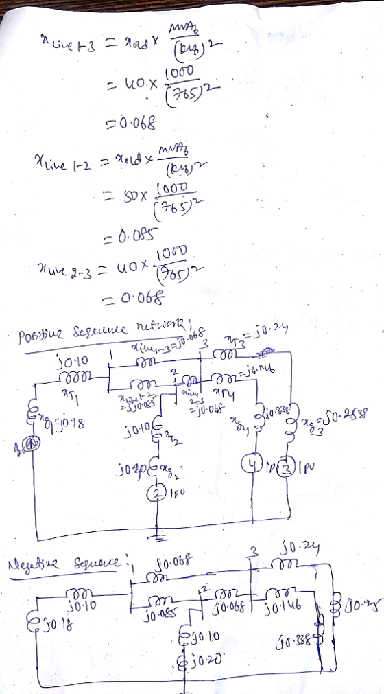
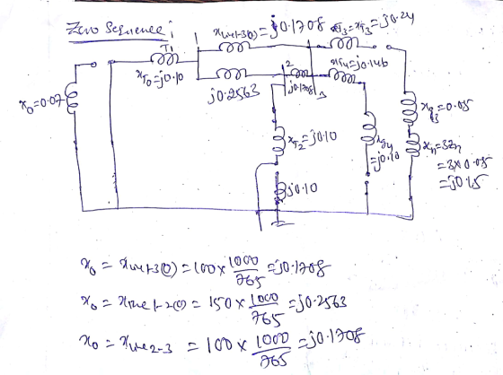
 3) The single-line diagram of a three-phase power system is shown in Fig. 1. Equipment ratings are given as follows: G1 1,000 MVA, 15.0 kV, 20.18, o 0.07 pu G2 : 1,000 MVA. 15.0 kV, 攻=エ1 =エ2 = 0.20, ro = 0.10 pu G3 : 500 MVA, 13.8 kV. 1" = 띠 z2 = 0.15, zo 0.05 pu G4 : 750 MVA, 13.8 kV. ェd =ェ1 = 0.30, T2 = 0.40 ro = 0.10 pu Ti : 1,000 MVA. 15.0Δ/765Y...
A single line diagram of a power system is shown in Fig. 2. The system data with equipment ratings and assumed sequence reactances are given the following table. The neutrals of the generator and A-Y...
 A single line diagram of a power system is shown in Fig. 2. The system data with equipment ratings and assumed sequence reactances are given the following table. The neutrals of the generator and A-Y transformers are solidly grounded. The motor neutral is grounded through a reactance Xn 0.05 per unit on the motor base. Assume that Pre-fault voltage is takin as VF-1.0 ,0° per unit and Pre- fault load current and Δ-Y transformer phase shift are neglected In the...
the single-line diagram of a three-phase power system is shown in figure 9.17. equipment ratings are...
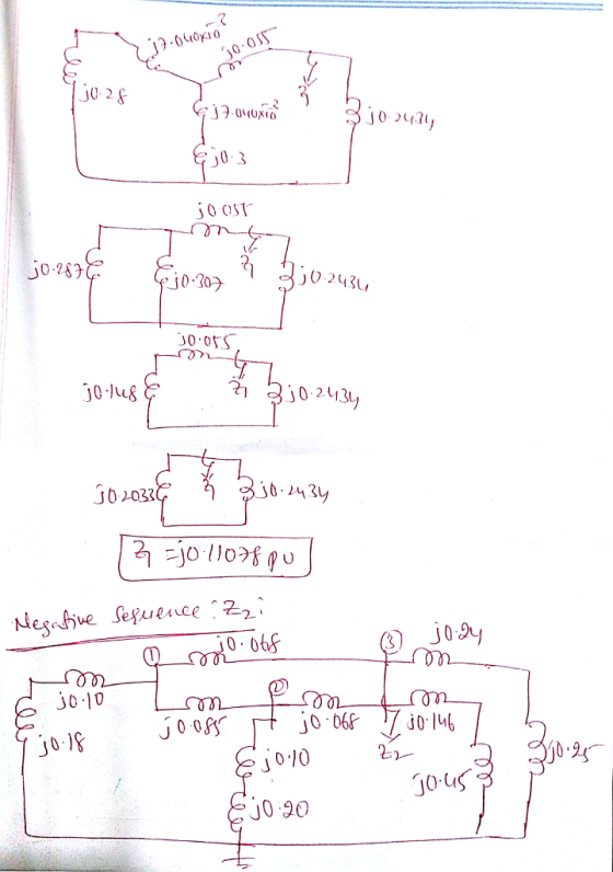
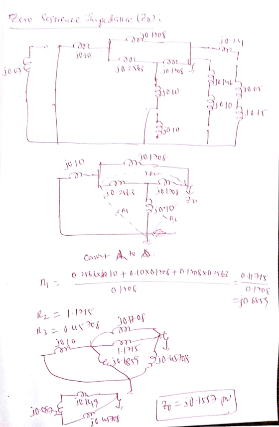
 the single-line diagram of a three-phase power system is shown in figure 9.17. equipment ratings are given as follows: The inductor connected to Generator 3 neutral has a reactance of 0.05 per unit using generator 3 ratings as a base. Draw the zero-, positive-, and negative-sequence reactance diagrams using a 1000-MVA, 765-kV base in the zone of line 1-2. Neglect the Δ—Y. transformer phase shifts.
Problem 7. Three-phase Balanced Fault Analysis. For the two-generator system below, a three-phase short occurs at point A. Ignoring prefault currents and assuming a prefault bus voltage of 1.0 р.u.,...
 Problem 7. Three-phase Balanced Fault Analysis. For the two-generator system below, a three-phase short occurs at point A. Ignoring prefault currents and assuming a prefault bus voltage of 1.0 р.u., determine the fault current, in kA, contributed from generator G Assume base values of 50 MVA and 50 kV on transmission line side. 25 kV 50 MVA, 2.5% 1:2 50 MVA, 2090 25 kV 75.MVA, 15% г,-0.4% Figure 1
Problem 7. Three-phase Balanced Fault Analysis. For the two-generator system below,...
Problem 7. Three-phase Balanced Fault Analysis. For the two-generator system below, a three-phase short occurs at point A. Ignoring prefault currents and assuming a prefault bus voltage of 1.0 р.u., determine the fault current, in kA, contributed from generator G Assume base values of 50 MVA and 50 kV on transmission line side. 25 kV 50 MVA, 2.5% 1:2 50 MVA, 2090 25 kV 75.MVA, 15% г,-0.4% Figure 1
Problem 7. Three-phase Balanced Fault Analysis. For the two-generator system below,...
The ratings of the components shown in the one-line diagram are G1: 25 MVA, 13.8 kV, x-0.15 pu G2:15MVA, 13 kV, x = 0.1 5 pu. TI : 25 MVA, 13.2/69 kV, x-0. I 1 pu T2: 25 MVA, 69/13.2 kV,x-0.220 pu Tr...
 The ratings of the components shown in the one-line diagram are G1: 25 MVA, 13.8 kV, x-0.15 pu G2:15MVA, 13 kV, x = 0.1 5 pu. TI : 25 MVA, 13.2/69 kV, x-0. I 1 pu T2: 25 MVA, 69/13.2 kV,x-0.220 pu Transmission line: j65 ohms/pha bus 2 BE 165Ω ISMVA e ratings of generator 1 as base valu 25MVA 13.8 kV 1 5% 69113.2 kV13kV 1 1% 13.2169k 1 1% 1- Draw the reactance diagram. 2- Find the Y-bus...
 Transformer TI : 50 MVA, 10 kV Y/138 kV Y, X=0.10 per unit; Transformer T2: 100 MVA, 15 kV D/138 kV Y, X-0.10 per unit; Each 138-kV line: X1-400 A three-phase short circuit occurs at bus 5, where the prefault voltage is 15 kV. Prefault load current is neglected. (a)Draw the positive-sequence reactance diagram in per-unit on a 100-MVA, 15-kV base in the zone of generator G2. Determine: (b) the The'venin equivalent at the fault, (c) the subtransient fault current...
 QUESTION 4. A single-line diagram of a power system is shown in Figure Q3 below, where negative and zero-sequence reactances are also given. The neutrals of the generator and A-Y transformers are solidly grounded. The motor neutral is grounded through a reactance X.=0.05 per unit on the motor base. Prefault voltage is VF1.05<Oº per unit whereas prefault load current is zero. Take A-Y transformer phase shifts into consideration. M Line tool X, - X2 - 200 100 MVA X =...
 Four-bus power system shown in Fig. 1 are as follows: Generator G1: 200 MVA, 7.2 kv, X -0.15 p.u Generator G2: 250 MVA, 9.6 kV, X-0.12 p.u Generator G3: 500 MVA, 10 kV, X-0.25 p.u Transformer T1:200 MVA, 7.2 Δ /132 Y kV, X= 0.05 p.u Transformer T2: 250 MVA, 9.6 Δ /132 Y kV, X =0.15 p.u Transformer T3: 500 MVA, 10 Δ /132 Y kV, x-0.1 p.u Each 132-kV line:X,-10 Ω 1- A three-phase short circuit occurs at...
 2. A single-line diagram of the power system considered is shown in Figure P2a, where negative- and zero-sequence reactances are also given. The neutrals of the generator and A-Y transformers are solidly grounded. The motor neutral is grounded through a reactance Xn = 0.05 per unit on the motor base. The per-unit zero-, positive and negative-sequence networks on a 100-MVA is shown in Figure P26, 13.8-kV base in the zone of the generator. a. Reduce the sequence networks to their...
 3) The single-line diagram of a three-phase power system is shown in Fig. 1. Equipment ratings are given as follows: G1 1,000 MVA, 15.0 kV, 20.18, o 0.07 pu G2 : 1,000 MVA. 15.0 kV, 攻=エ1 =エ2 = 0.20, ro = 0.10 pu G3 : 500 MVA, 13.8 kV. 1" = 띠 z2 = 0.15, zo 0.05 pu G4 : 750 MVA, 13.8 kV. ェd =ェ1 = 0.30, T2 = 0.40 ro = 0.10 pu Ti : 1,000 MVA. 15.0Δ/765Y...
 A single line diagram of a power system is shown in Fig. 2. The system data with equipment ratings and assumed sequence reactances are given the following table. The neutrals of the generator and A-Y transformers are solidly grounded. The motor neutral is grounded through a reactance Xn 0.05 per unit on the motor base. Assume that Pre-fault voltage is takin as VF-1.0 ,0° per unit and Pre- fault load current and Δ-Y transformer phase shift are neglected In the...
 the single-line diagram of a three-phase power system is shown in figure 9.17. equipment ratings are given as follows: The inductor connected to Generator 3 neutral has a reactance of 0.05 per unit using generator 3 ratings as a base. Draw the zero-, positive-, and negative-sequence reactance diagrams using a 1000-MVA, 765-kV base in the zone of line 1-2. Neglect the Δ—Y. transformer phase shifts.
 Problem 7. Three-phase Balanced Fault Analysis. For the two-generator system below, a three-phase short occurs at point A. Ignoring prefault currents and assuming a prefault bus voltage of 1.0 р.u., determine the fault current, in kA, contributed from generator G Assume base values of 50 MVA and 50 kV on transmission line side. 25 kV 50 MVA, 2.5% 1:2 50 MVA, 2090 25 kV 75.MVA, 15% г,-0.4% Figure 1
Problem 7. Three-phase Balanced Fault Analysis. For the two-generator system below,...
Problem 7. Three-phase Balanced Fault Analysis. For the two-generator system below, a three-phase short occurs at point A. Ignoring prefault currents and assuming a prefault bus voltage of 1.0 р.u., determine the fault current, in kA, contributed from generator G Assume base values of 50 MVA and 50 kV on transmission line side. 25 kV 50 MVA, 2.5% 1:2 50 MVA, 2090 25 kV 75.MVA, 15% г,-0.4% Figure 1
Problem 7. Three-phase Balanced Fault Analysis. For the two-generator system below,...
 The ratings of the components shown in the one-line diagram are G1: 25 MVA, 13.8 kV, x-0.15 pu G2:15MVA, 13 kV, x = 0.1 5 pu. TI : 25 MVA, 13.2/69 kV, x-0. I 1 pu T2: 25 MVA, 69/13.2 kV,x-0.220 pu Transmission line: j65 ohms/pha bus 2 BE 165Ω ISMVA e ratings of generator 1 as base valu 25MVA 13.8 kV 1 5% 69113.2 kV13kV 1 1% 13.2169k 1 1% 1- Draw the reactance diagram. 2- Find the Y-bus...
Most questions answered within 3 hours.
-
You have a yeast cell culture with a concentration of 5x10^4
cells/ml. If you dilute this...
asked 38 seconds from now -
In which direction the Reaction goes? Show detailed process.
SeO3 + 2ClO2. + 2H3O <---> Se...
asked 12 minutes ago -
Unexposed silver halides are removed from photographic film when
they react with sodium thiosulfate
(Na2S2O3, called...
asked 13 minutes ago -
A 0.3054 gram sample of the mineral chalcopyrite (CuFeS2)
yielded 0.6525 gram BaSO4 precipitate. What is...
asked 13 minutes ago -
An short-seller in Tesla is worried the latest management
earnings forecast is too aggressive and the...
asked 59 minutes ago -
Question 3 (1 point)
Fill in the blank. Speed Car Rental company found that the tire...
asked 59 minutes ago -
1. A copper wire is 26.61 cm long and weighs 1.265 g. The
density of copper...
asked 36 minutes ago -
Remember that a concept sketch consists of a sketch (or
series of sketches), labels, and complete...
asked 39 minutes ago -
on a newly discovered planet, the period of a pendulum with a
length of 2 m...
asked 41 minutes ago -
Why [M(CN)6] is not organometallic even it has metal
to carbon bond too
asked 47 minutes ago -
mstar electric has a bond issue outstanding that has a 20 year
life, a $1,000 par...
asked 55 minutes ago -
This is a Business Writing Question:
Common Types of Faulty Sentence Logic:
A. Mixed constructions
B....
asked 56 minutes ago