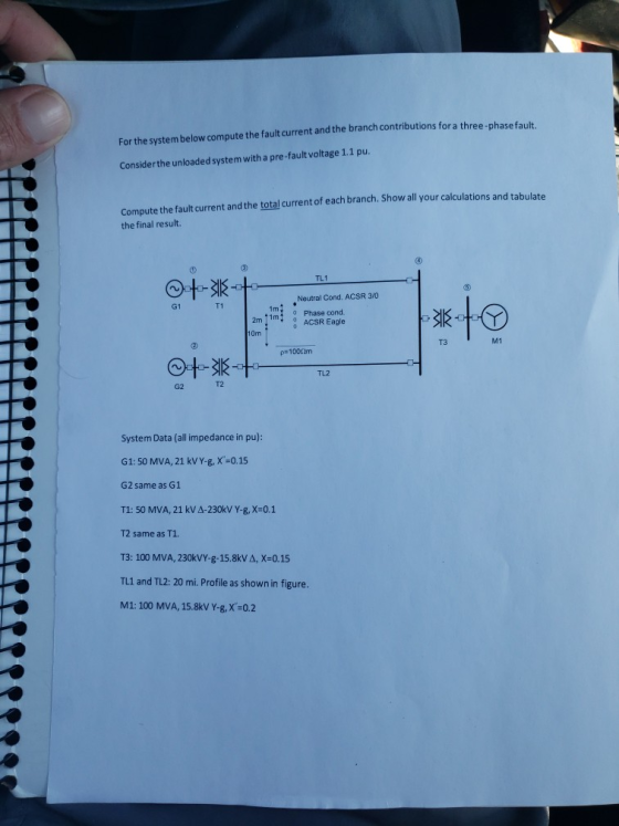
For the system below compute the fault current and the branch contributions for a three phase fault.
consider the unloaded system with a pre-fault voltage of 1.1 pu.
Compute the fault current and the total current of each branch. Show all calculations and tabulate the final result.
Homework Answers
Request Answer!
We need at least 10 more requests to produce the answer.
0 / 10 have requested this problem solution
The more requests, the faster the answer.
Add Answer to:
For the system below compute the fault current and the
branch contributions for a three phase...
For the network shown below, the pu reactance data are equivalent sequence circuit and calculate the fault current in p...
 For the network shown below, the pu reactance data are equivalent sequence circuit and calculate the fault current in per unit for a bolted single line- to-ground fault at bus 2. The pre-fault bus voltages are assumed to be 1 pu given in the table. Draw the Ti T2 1 2 3 G1 G2 5 X2 Item G1 0.10 0.10 0.05 0.05 G2 0.10 0.10 0.01 T1 0.01 0.01 0.01 T2 0.01 0.01 Line 2-3 0.10 0.10 0.20 Line 3-5...
Power System
A simple three-phase power system is shown in Figure 2. Assume that the ratings of the various devices in this system are as follows: • Generators G1, G2: 40 MVA, 13.2 kV, = 0.15 pu, = 0.15 pu, = 0.08 • Generator G3: 60 MVA, 13.8 kV, = 0.20 pu, 0.20 pu, - 0.08 • Transformers T1, T2, T3, T4: 40 MVA, 13.8/138 kV, X1 = X2 = 0.10 pu, XO 0.08 pu Transformers T5, T6: 30 MVA, 13.8/138 kV, X1 = X2...
3.13 A single-line diagram of a three-phase power system is shown in Fig. 3.51. The ratings...
 3.13 A single-line diagram of a three-phase power system is shown in Fig. 3.51. The ratings of the equipment are shown below Generator G: 100 MVA, 11 kV, Xi -X2-0.20 pu, Xo -0.05 pu Generator G2 : 100 MVA, 20 kV, Xi=X2=0.25 pu, Xo=0.03 pu, X,,-0.05 pu Transformer T: 100 MVA, 11/66 kV, Xi -X2-Xo 0.06 pu Transformer T2: 100 MVA, 11/66 kV, Xi-X2 = Xo 0.06 pu Line: 100 MVA, X,-X2 = 0.15 pu, Xo = 0.65 pu A...
The component parameters for the power system shown in Figure 2 are given in Table 1. The pre-fau...
 The component parameters for the power system shown in Figure 2 are given in Table 1. The pre-fault voltage is 120° pu and Zx-j0.1 pu. Table 1 Ratings X2-Xi (pu)Xo (pu) 0.05 0.10 0.20 0.20 Components G1, G2 200 MVA, 20 kV 0.10 0.10 0.10 0.10 T1, T2, T3200 MVA, 20/200 kV L1 200 MVA, 200 kV し2 200 MVA, 20 kV (a) Draw the three sequence networks and determine the per-unit Thevenin impedance of each sequence network seen from...
Four-bus power system shown in Fig. 1 are as follows: Generator G1: 200 MVA, 7.2 kv,...
 Four-bus power system shown in Fig. 1 are as follows: Generator G1: 200 MVA, 7.2 kv, X -0.15 p.u Generator G2: 250 MVA, 9.6 kV, X-0.12 p.u Generator G3: 500 MVA, 10 kV, X-0.25 p.u Transformer T1:200 MVA, 7.2 Δ /132 Y kV, X= 0.05 p.u Transformer T2: 250 MVA, 9.6 Δ /132 Y kV, X =0.15 p.u Transformer T3: 500 MVA, 10 Δ /132 Y kV, x-0.1 p.u Each 132-kV line:X,-10 Ω 1- A three-phase short circuit occurs at...
can you calculating this question and explain why? thanks The ratings and sequence reactances of the components for...
 can you calculating this question and explain why?
thanks
The ratings and sequence reactances of the components for the power system shown in Figure 2 are given in Table 1. The pre-fault voltage is 1/0° per unit (pu). Bus 8 L3 Bus 1 T1 Bus 4 T2 Bus 2 Bus 5 L1 L2 G1 Bus 3 T3 Bus 7 Bus 6 D.6975 Figure Draw the per unit impedance sequence networks and determine the per unit (a) Thevenin impedances of the...
can you calculating this question and explain why?
thanks
The ratings and sequence reactances of the components for the power system shown in Figure 2 are given in Table 1. The pre-fault voltage is 1/0° per unit (pu). Bus 8 L3 Bus 1 T1 Bus 4 T2 Bus 2 Bus 5 L1 L2 G1 Bus 3 T3 Bus 7 Bus 6 D.6975 Figure Draw the per unit impedance sequence networks and determine the per unit (a) Thevenin impedances of the...
Transformer TI : 50 MVA, 10 kV Y/138 kV Y, X=0.10 per unit; Transformer T2: 100 MVA, 15 kV D/138 kV Y, X-0.10 per unit; Each 138-kV line: X1-400 A three-phase short circuit occurs at bus 5,...
 Transformer TI : 50 MVA, 10 kV Y/138 kV Y, X=0.10 per unit; Transformer T2: 100 MVA, 15 kV D/138 kV Y, X-0.10 per unit; Each 138-kV line: X1-400 A three-phase short circuit occurs at bus 5, where the prefault voltage is 15 kV. Prefault load current is neglected. (a)Draw the positive-sequence reactance diagram in per-unit on a 100-MVA, 15-kV base in the zone of generator G2. Determine: (b) the The'venin equivalent at the fault, (c) the subtransient fault current...
Q6: For the system shown in Figure below. Calculate the short circuit curTent for a symmetrical phase fault at point F: use a 100MVA base. T1 115 kV TL 50 km 0.4 Ω/km Reactor T2 Power Sys G2 G1&G...
 Q6: For the system shown in Figure below. Calculate the short circuit curTent for a symmetrical phase fault at point F: use a 100MVA base. T1 115 kV TL 50 km 0.4 Ω/km Reactor T2 Power Sys G2 G1&G2-75MVA, 10.5kV, 13.2% T1&T2-60MVA, 10.5% Reactor-60MVA, 9% Power Sys-2000MVA, 8000
Q6: For the system shown in Figure below. Calculate the short circuit curTent for a symmetrical phase fault at point F: use a 100MVA base. T1 115 kV TL 50 km 0.4...
Q6: For the system shown in Figure below. Calculate the short circuit curTent for a symmetrical phase fault at point F: use a 100MVA base. T1 115 kV TL 50 km 0.4 Ω/km Reactor T2 Power Sys G2 G1&G2-75MVA, 10.5kV, 13.2% T1&T2-60MVA, 10.5% Reactor-60MVA, 9% Power Sys-2000MVA, 8000
Q6: For the system shown in Figure below. Calculate the short circuit curTent for a symmetrical phase fault at point F: use a 100MVA base. T1 115 kV TL 50 km 0.4...
The ratings of the components shown in the one-line diagram are G1: 25 MVA, 13.8 kV, x-0.15 pu G2:15MVA, 13 kV, x = 0.1 5 pu. TI : 25 MVA, 13.2/69 kV, x-0. I 1 pu T2: 25 MVA, 69/13.2 kV,x-0.220 pu Tr...
 The ratings of the components shown in the one-line diagram are G1: 25 MVA, 13.8 kV, x-0.15 pu G2:15MVA, 13 kV, x = 0.1 5 pu. TI : 25 MVA, 13.2/69 kV, x-0. I 1 pu T2: 25 MVA, 69/13.2 kV,x-0.220 pu Transmission line: j65 ohms/pha bus 2 BE 165Ω ISMVA e ratings of generator 1 as base valu 25MVA 13.8 kV 1 5% 69113.2 kV13kV 1 1% 13.2169k 1 1% 1- Draw the reactance diagram. 2- Find the Y-bus...
The Fig. P1.1 is a one-line diagram of a simple power system. There prefault system is...
 The Fig. P1.1 is a one-line diagram of a simple power system. There prefault system is on no-load with 1.0 pu voltage and prefault currents are zero. A BOLTED THREE-PHASE FAULT occurs at point P. (a) Draw the pre-fault single-phase equivalent circuit showing numerical values. (b) (i) Calculate the subtransient current in the fault (ii) Calculate the voltages at the busses during the fault. (iii)Calculate the e subtransient current in the lines. (c)) Determine the Zbus relating the bus currents...
 For the network shown below, the pu reactance data are equivalent sequence circuit and calculate the fault current in per unit for a bolted single line- to-ground fault at bus 2. The pre-fault bus voltages are assumed to be 1 pu given in the table. Draw the Ti T2 1 2 3 G1 G2 5 X2 Item G1 0.10 0.10 0.05 0.05 G2 0.10 0.10 0.01 T1 0.01 0.01 0.01 T2 0.01 0.01 Line 2-3 0.10 0.10 0.20 Line 3-5...
 3.13 A single-line diagram of a three-phase power system is shown in Fig. 3.51. The ratings of the equipment are shown below Generator G: 100 MVA, 11 kV, Xi -X2-0.20 pu, Xo -0.05 pu Generator G2 : 100 MVA, 20 kV, Xi=X2=0.25 pu, Xo=0.03 pu, X,,-0.05 pu Transformer T: 100 MVA, 11/66 kV, Xi -X2-Xo 0.06 pu Transformer T2: 100 MVA, 11/66 kV, Xi-X2 = Xo 0.06 pu Line: 100 MVA, X,-X2 = 0.15 pu, Xo = 0.65 pu A...
 The component parameters for the power system shown in Figure 2 are given in Table 1. The pre-fault voltage is 120° pu and Zx-j0.1 pu. Table 1 Ratings X2-Xi (pu)Xo (pu) 0.05 0.10 0.20 0.20 Components G1, G2 200 MVA, 20 kV 0.10 0.10 0.10 0.10 T1, T2, T3200 MVA, 20/200 kV L1 200 MVA, 200 kV し2 200 MVA, 20 kV (a) Draw the three sequence networks and determine the per-unit Thevenin impedance of each sequence network seen from...
 Four-bus power system shown in Fig. 1 are as follows: Generator G1: 200 MVA, 7.2 kv, X -0.15 p.u Generator G2: 250 MVA, 9.6 kV, X-0.12 p.u Generator G3: 500 MVA, 10 kV, X-0.25 p.u Transformer T1:200 MVA, 7.2 Δ /132 Y kV, X= 0.05 p.u Transformer T2: 250 MVA, 9.6 Δ /132 Y kV, X =0.15 p.u Transformer T3: 500 MVA, 10 Δ /132 Y kV, x-0.1 p.u Each 132-kV line:X,-10 Ω 1- A three-phase short circuit occurs at...
 can you calculating this question and explain why?
thanks
The ratings and sequence reactances of the components for the power system shown in Figure 2 are given in Table 1. The pre-fault voltage is 1/0° per unit (pu). Bus 8 L3 Bus 1 T1 Bus 4 T2 Bus 2 Bus 5 L1 L2 G1 Bus 3 T3 Bus 7 Bus 6 D.6975 Figure Draw the per unit impedance sequence networks and determine the per unit (a) Thevenin impedances of the...
can you calculating this question and explain why?
thanks
The ratings and sequence reactances of the components for the power system shown in Figure 2 are given in Table 1. The pre-fault voltage is 1/0° per unit (pu). Bus 8 L3 Bus 1 T1 Bus 4 T2 Bus 2 Bus 5 L1 L2 G1 Bus 3 T3 Bus 7 Bus 6 D.6975 Figure Draw the per unit impedance sequence networks and determine the per unit (a) Thevenin impedances of the...
 Transformer TI : 50 MVA, 10 kV Y/138 kV Y, X=0.10 per unit; Transformer T2: 100 MVA, 15 kV D/138 kV Y, X-0.10 per unit; Each 138-kV line: X1-400 A three-phase short circuit occurs at bus 5, where the prefault voltage is 15 kV. Prefault load current is neglected. (a)Draw the positive-sequence reactance diagram in per-unit on a 100-MVA, 15-kV base in the zone of generator G2. Determine: (b) the The'venin equivalent at the fault, (c) the subtransient fault current...
 Q6: For the system shown in Figure below. Calculate the short circuit curTent for a symmetrical phase fault at point F: use a 100MVA base. T1 115 kV TL 50 km 0.4 Ω/km Reactor T2 Power Sys G2 G1&G2-75MVA, 10.5kV, 13.2% T1&T2-60MVA, 10.5% Reactor-60MVA, 9% Power Sys-2000MVA, 8000
Q6: For the system shown in Figure below. Calculate the short circuit curTent for a symmetrical phase fault at point F: use a 100MVA base. T1 115 kV TL 50 km 0.4...
Q6: For the system shown in Figure below. Calculate the short circuit curTent for a symmetrical phase fault at point F: use a 100MVA base. T1 115 kV TL 50 km 0.4 Ω/km Reactor T2 Power Sys G2 G1&G2-75MVA, 10.5kV, 13.2% T1&T2-60MVA, 10.5% Reactor-60MVA, 9% Power Sys-2000MVA, 8000
Q6: For the system shown in Figure below. Calculate the short circuit curTent for a symmetrical phase fault at point F: use a 100MVA base. T1 115 kV TL 50 km 0.4...
 The ratings of the components shown in the one-line diagram are G1: 25 MVA, 13.8 kV, x-0.15 pu G2:15MVA, 13 kV, x = 0.1 5 pu. TI : 25 MVA, 13.2/69 kV, x-0. I 1 pu T2: 25 MVA, 69/13.2 kV,x-0.220 pu Transmission line: j65 ohms/pha bus 2 BE 165Ω ISMVA e ratings of generator 1 as base valu 25MVA 13.8 kV 1 5% 69113.2 kV13kV 1 1% 13.2169k 1 1% 1- Draw the reactance diagram. 2- Find the Y-bus...
 The Fig. P1.1 is a one-line diagram of a simple power system. There prefault system is on no-load with 1.0 pu voltage and prefault currents are zero. A BOLTED THREE-PHASE FAULT occurs at point P. (a) Draw the pre-fault single-phase equivalent circuit showing numerical values. (b) (i) Calculate the subtransient current in the fault (ii) Calculate the voltages at the busses during the fault. (iii)Calculate the e subtransient current in the lines. (c)) Determine the Zbus relating the bus currents...
Most questions answered within 3 hours.
-
Phosphorous + bromine = phosphorous tribromide. If 35.0 g of
bromine are reacted and 27.9 grams...
asked 1 hour ago -
Derive the long wavelength limit of the Planck energy density
distribution
asked 1 hour ago -
Calculate the pH of each of the following solutions.
0.50 M HBr
3.1×10⁻⁴ M KOH
4.2×10⁻⁵...
asked 4 hours ago -
For the year ended December 31, Depot Max’s cost of merchandise
sold was $85,600. Inventory at the...
asked 4 hours ago -
Week 10 - Professional Memo Assignment
Professional Memo Assignment
Your mission for this week, should you...
asked 4 hours ago -
Write a Python program that stores the data for each
player on the team, and it...
asked 4 hours ago -
In
the last 3 months, mike never knows when he is going to get his
allowance...
asked 5 hours ago -
Is Ca(OH)2 a Bronsted base, Lewis base, or both? Why?
asked 5 hours ago -
1A- Why don’t voters complain about U.S. tariffs on imported
sugar?
Because sugar is only a...
asked 5 hours ago -
Cash Payback Period
Primera Banco is evaluating two capital investment proposals for
a drive-up ATM kiosk,...
asked 5 hours ago -
Create a button in Swift (Xcode) that will create a charge,
create a charge using Stripe's...
asked 5 hours ago -
The reaction rate of CO and NO2 in the reaction
CO(g) + NO2(g) → CO2(g) +...
asked 5 hours ago