can you calculating this question and explain why? thanks
Homework Answers


Add Answer to:
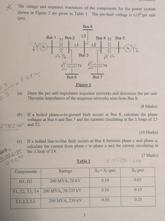
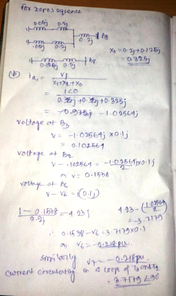
can you calculating this question and explain why? thanks The ratings and sequence reactances of the components for...
The component parameters for the power system shown in Figure 2 are given in Table 1. The pre-fau...
 The component parameters for the power system shown in Figure 2 are given in Table 1. The pre-fault voltage is 120° pu and Zx-j0.1 pu. Table 1 Ratings X2-Xi (pu)Xo (pu) 0.05 0.10 0.20 0.20 Components G1, G2 200 MVA, 20 kV 0.10 0.10 0.10 0.10 T1, T2, T3200 MVA, 20/200 kV L1 200 MVA, 200 kV し2 200 MVA, 20 kV (a) Draw the three sequence networks and determine the per-unit Thevenin impedance of each sequence network seen from...
Q3: (15 Points) Equi below are given as follows: pment ratings and per-unit reactances for the sy...
 Q3: (15 Points) Equi below are given as follows: pment ratings and per-unit reactances for the system shown in circuit 2 4 T1 TL12 T2b G1 G2 TL13 TL23 0.03 j0.03 Synchronous Generators: G1 100 MVA 25 kV G2 100 MVA 3.8 kV Transformers: T1 100 MVA 25/230 kV T2 100 MVA 13.8 /230 kV X1=X2= 0.2 X0-0.05 X1-X2-0.2 X0 0.05 X1 = X2-X0 = 0.05 Transmission lines: TL12 100 MVA TL13 100 MVA TL23 100 MVA X0 0.3 XO...
A 7-bus power system with three generators, six transformers, and seven transmission lines is shown in...
 A 7-bus power system with three generators, six transformers, and seven transmission lines is shown in Figure Q1. The per-unit reactances for the generators and transfomers are based on their rated voltage and expressed in percentage. When a three-phase fault occurs at bus 5; three transmission lines, namely L4, L5, and L6, are disconnected from the power system. By taking the base apparent power of 100 MVA and the rated voltage of generator G1 as the reference, determine the per-unit...
A single line diagram of a power system is shown in Fig. 2. The system data with equipment ratings and assumed sequence reactances are given the following table. The neutrals of the generator and A-Y...
 A single line diagram of a power system is shown in Fig. 2. The system data with equipment ratings and assumed sequence reactances are given the following table. The neutrals of the generator and A-Y transformers are solidly grounded. The motor neutral is grounded through a reactance Xn 0.05 per unit on the motor base. Assume that Pre-fault voltage is takin as VF-1.0 ,0° per unit and Pre- fault load current and Δ-Y transformer phase shift are neglected In the...
Power System
A simple three-phase power system is shown in Figure 2. Assume that the ratings of the various devices in this system are as follows: • Generators G1, G2: 40 MVA, 13.2 kV, = 0.15 pu, = 0.15 pu, = 0.08 • Generator G3: 60 MVA, 13.8 kV, = 0.20 pu, 0.20 pu, - 0.08 • Transformers T1, T2, T3, T4: 40 MVA, 13.8/138 kV, X1 = X2 = 0.10 pu, XO 0.08 pu Transformers T5, T6: 30 MVA, 13.8/138 kV, X1 = X2...
BUS 1 BUS 2 LINE 1 T1 L1 T2 G1 G2 R = 0,6 pu LINE 2 L2 T3 G3 BUS 3 a) For the above network, draw positive, negative an...
 BUS 1 BUS 2 LINE 1 T1 L1 T2 G1 G2 R = 0,6 pu LINE 2 L2 T3 G3 BUS 3 a) For the above network, draw positive, negative and zero sequence networks (60 marks) b) Provide the main mathematical steps that will allow you to calculate the magnitude (in ampere) of the phase to phase fault current at BUS 1. As part of your answer you should show clearly, on a diagram, how the networks of part (a)...
No calculations needed, just use written labels given. BUS 1 BUS 2 LINE 1 T1 L1 T2. G1 G2 R= 0.6 pu LINE 2 L2 T3 G3 BUS...
 No calculations needed, just use written labels given.
BUS 1 BUS 2 LINE 1 T1 L1 T2. G1 G2 R= 0.6 pu LINE 2 L2 T3 G3 BUS 3 a) For the above network, draw positive, negative and zero sequence networks (40 marks) b) Provide the main mathematical steps that will allow you to calculate the magnitude (in ampere) of the phase to ground fault at the midpoint of line 1 As part of your answer you should show clearly,...
No calculations needed, just use written labels given.
BUS 1 BUS 2 LINE 1 T1 L1 T2. G1 G2 R= 0.6 pu LINE 2 L2 T3 G3 BUS 3 a) For the above network, draw positive, negative and zero sequence networks (40 marks) b) Provide the main mathematical steps that will allow you to calculate the magnitude (in ampere) of the phase to ground fault at the midpoint of line 1 As part of your answer you should show clearly,...
Problem 1. Equipment ratings and per-unit reactances for the system shown in figure 1. are given...
 Problem 1. Equipment ratings and per-unit reactances for the system shown in figure 1. are given as follows Using a 100-MVA, 230-kV base for the transmission lines, draw the per-unit sequence networks Consider the impact of ?-Y phase shifts Synchronous generators: G 100 MVA 25kV X1-X2 0.2Xo 0.05 G2100 MVA 13.8 kV X,-X2 0.2 Xo 0.05 Transformers: TI 100 MVA 25/230 kV Xi-X-Xo-0.05 T2 100 MVA 13.8/230 kV X-X2 = Xo 0.05 Transmission lines: TL 12 100MVA 230 kV X,=X2=0.1...
The ratings of the components shown in the one-line diagram are G1: 25 MVA, 13.8 kV, x-0.15 pu G2:15MVA, 13 kV, x = 0.1 5 pu. TI : 25 MVA, 13.2/69 kV, x-0. I 1 pu T2: 25 MVA, 69/13.2 kV,x-0.220 pu Tr...
 The ratings of the components shown in the one-line diagram are G1: 25 MVA, 13.8 kV, x-0.15 pu G2:15MVA, 13 kV, x = 0.1 5 pu. TI : 25 MVA, 13.2/69 kV, x-0. I 1 pu T2: 25 MVA, 69/13.2 kV,x-0.220 pu Transmission line: j65 ohms/pha bus 2 BE 165Ω ISMVA e ratings of generator 1 as base valu 25MVA 13.8 kV 1 5% 69113.2 kV13kV 1 1% 13.2169k 1 1% 1- Draw the reactance diagram. 2- Find the Y-bus...
1. For the following three-phase network, draw the positive sequence diagram and the zero sequenc...
 1. For the following three-phase network, draw the positive sequence diagram and the zero sequence diagram. Choose a system base of 120 MVA, 154 KV in the L1 portion of the system. Next, find the thevenin impedance at Bus A (in pu) for both the positive sequence and zero sequence diagrams G 1: 1 3.2KV, 80 MVA, XI-X2-9%, X0-6%, xn-4% on gen rating T1: 1 3.8KV delta/161 KV Wye, 60 MVA, X-9% T1 Bus A L1 G1 Xn
1. For...
1. For the following three-phase network, draw the positive sequence diagram and the zero sequence diagram. Choose a system base of 120 MVA, 154 KV in the L1 portion of the system. Next, find the thevenin impedance at Bus A (in pu) for both the positive sequence and zero sequence diagrams G 1: 1 3.2KV, 80 MVA, XI-X2-9%, X0-6%, xn-4% on gen rating T1: 1 3.8KV delta/161 KV Wye, 60 MVA, X-9% T1 Bus A L1 G1 Xn
1. For...
 The component parameters for the power system shown in Figure 2 are given in Table 1. The pre-fault voltage is 120° pu and Zx-j0.1 pu. Table 1 Ratings X2-Xi (pu)Xo (pu) 0.05 0.10 0.20 0.20 Components G1, G2 200 MVA, 20 kV 0.10 0.10 0.10 0.10 T1, T2, T3200 MVA, 20/200 kV L1 200 MVA, 200 kV し2 200 MVA, 20 kV (a) Draw the three sequence networks and determine the per-unit Thevenin impedance of each sequence network seen from...
 Q3: (15 Points) Equi below are given as follows: pment ratings and per-unit reactances for the system shown in circuit 2 4 T1 TL12 T2b G1 G2 TL13 TL23 0.03 j0.03 Synchronous Generators: G1 100 MVA 25 kV G2 100 MVA 3.8 kV Transformers: T1 100 MVA 25/230 kV T2 100 MVA 13.8 /230 kV X1=X2= 0.2 X0-0.05 X1-X2-0.2 X0 0.05 X1 = X2-X0 = 0.05 Transmission lines: TL12 100 MVA TL13 100 MVA TL23 100 MVA X0 0.3 XO...
 A 7-bus power system with three generators, six transformers, and seven transmission lines is shown in Figure Q1. The per-unit reactances for the generators and transfomers are based on their rated voltage and expressed in percentage. When a three-phase fault occurs at bus 5; three transmission lines, namely L4, L5, and L6, are disconnected from the power system. By taking the base apparent power of 100 MVA and the rated voltage of generator G1 as the reference, determine the per-unit...
 A single line diagram of a power system is shown in Fig. 2. The system data with equipment ratings and assumed sequence reactances are given the following table. The neutrals of the generator and A-Y transformers are solidly grounded. The motor neutral is grounded through a reactance Xn 0.05 per unit on the motor base. Assume that Pre-fault voltage is takin as VF-1.0 ,0° per unit and Pre- fault load current and Δ-Y transformer phase shift are neglected In the...
 BUS 1 BUS 2 LINE 1 T1 L1 T2 G1 G2 R = 0,6 pu LINE 2 L2 T3 G3 BUS 3 a) For the above network, draw positive, negative and zero sequence networks (60 marks) b) Provide the main mathematical steps that will allow you to calculate the magnitude (in ampere) of the phase to phase fault current at BUS 1. As part of your answer you should show clearly, on a diagram, how the networks of part (a)...
 No calculations needed, just use written labels given.
BUS 1 BUS 2 LINE 1 T1 L1 T2. G1 G2 R= 0.6 pu LINE 2 L2 T3 G3 BUS 3 a) For the above network, draw positive, negative and zero sequence networks (40 marks) b) Provide the main mathematical steps that will allow you to calculate the magnitude (in ampere) of the phase to ground fault at the midpoint of line 1 As part of your answer you should show clearly,...
No calculations needed, just use written labels given.
BUS 1 BUS 2 LINE 1 T1 L1 T2. G1 G2 R= 0.6 pu LINE 2 L2 T3 G3 BUS 3 a) For the above network, draw positive, negative and zero sequence networks (40 marks) b) Provide the main mathematical steps that will allow you to calculate the magnitude (in ampere) of the phase to ground fault at the midpoint of line 1 As part of your answer you should show clearly,...
 Problem 1. Equipment ratings and per-unit reactances for the system shown in figure 1. are given as follows Using a 100-MVA, 230-kV base for the transmission lines, draw the per-unit sequence networks Consider the impact of ?-Y phase shifts Synchronous generators: G 100 MVA 25kV X1-X2 0.2Xo 0.05 G2100 MVA 13.8 kV X,-X2 0.2 Xo 0.05 Transformers: TI 100 MVA 25/230 kV Xi-X-Xo-0.05 T2 100 MVA 13.8/230 kV X-X2 = Xo 0.05 Transmission lines: TL 12 100MVA 230 kV X,=X2=0.1...
 The ratings of the components shown in the one-line diagram are G1: 25 MVA, 13.8 kV, x-0.15 pu G2:15MVA, 13 kV, x = 0.1 5 pu. TI : 25 MVA, 13.2/69 kV, x-0. I 1 pu T2: 25 MVA, 69/13.2 kV,x-0.220 pu Transmission line: j65 ohms/pha bus 2 BE 165Ω ISMVA e ratings of generator 1 as base valu 25MVA 13.8 kV 1 5% 69113.2 kV13kV 1 1% 13.2169k 1 1% 1- Draw the reactance diagram. 2- Find the Y-bus...
 1. For the following three-phase network, draw the positive sequence diagram and the zero sequence diagram. Choose a system base of 120 MVA, 154 KV in the L1 portion of the system. Next, find the thevenin impedance at Bus A (in pu) for both the positive sequence and zero sequence diagrams G 1: 1 3.2KV, 80 MVA, XI-X2-9%, X0-6%, xn-4% on gen rating T1: 1 3.8KV delta/161 KV Wye, 60 MVA, X-9% T1 Bus A L1 G1 Xn
1. For...
1. For the following three-phase network, draw the positive sequence diagram and the zero sequence diagram. Choose a system base of 120 MVA, 154 KV in the L1 portion of the system. Next, find the thevenin impedance at Bus A (in pu) for both the positive sequence and zero sequence diagrams G 1: 1 3.2KV, 80 MVA, XI-X2-9%, X0-6%, xn-4% on gen rating T1: 1 3.8KV delta/161 KV Wye, 60 MVA, X-9% T1 Bus A L1 G1 Xn
1. For...
Most questions answered within 3 hours.
-
how do radio waves get emitted from Jupiter?
- do they come from radiation from planet...
asked 13 seconds ago -
The test statistic used in the F test for the equality of two
variances is calculated...
asked 11 minutes ago -
How does neutralisation of IL-6 trans-signaling affect the
autoimmune disease and inflammation? What if the trans-signaling...
asked 1 minute ago -
f an allele is 'fixed' in a population, what is its
frequency?
0.50
0.75
0.25
0...
asked 16 minutes ago -
Do we have a duty of national loyalty in business? What is the
major argument in...
asked 16 minutes ago -
compare the international treatment of segment reporting to the
us gaap treatment
asked 12 minutes ago -
A statistics student finds herself struggling with a newspaper
article stating that only eighteen percent of...
asked 46 minutes ago -
People with beriberi, a disease caused by a thiamin deficiency,
have elevated levels of blood pyruvate...
asked 33 minutes ago -
PYTHON Programming Exercise 2: Create a Simple Cost Calculator
Write a program that displays input fields...
asked 39 minutes ago -
1.Seki agreed that Groupon could sell 18 hot air
balloon rides on his Magical Adventures company...
asked 40 minutes ago -
A cohort study is conducted to determine whether smoking is
associated with an increased risk of...
asked 45 minutes ago -
Create the pseudo-code/flowchart for an application class named
Monogram. Its main() method inputs three variables that...
asked 46 minutes ago