
Homework Answers

Add Answer to:
BUS 1 BUS 2 LINE 1 T1 L1 T2 G1 G2 R = 0,6 pu LINE 2 L2 T3 G3 BUS 3 a) For the above network, draw positive, negative an...
No calculations needed, just use written labels given. BUS 1 BUS 2 LINE 1 T1 L1 T2. G1 G2 R= 0.6 pu LINE 2 L2 T3 G3 BUS...
 No calculations needed, just use written labels given.
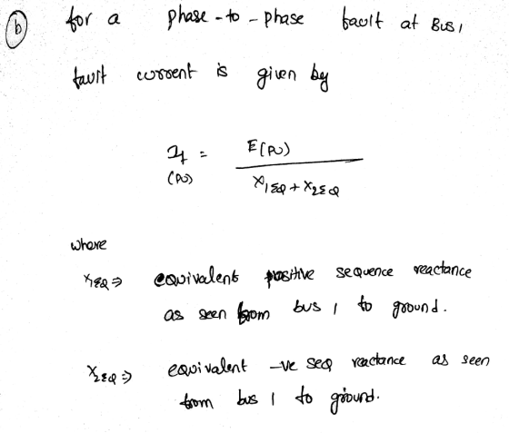
BUS 1 BUS 2 LINE 1 T1 L1 T2. G1 G2 R= 0.6 pu LINE 2 L2 T3 G3 BUS 3 a) For the above network, draw positive, negative and zero sequence networks (40 marks) b) Provide the main mathematical steps that will allow you to calculate the magnitude (in ampere) of the phase to ground fault at the midpoint of line 1 As part of your answer you should show clearly,...
No calculations needed, just use written labels given.
BUS 1 BUS 2 LINE 1 T1 L1 T2. G1 G2 R= 0.6 pu LINE 2 L2 T3 G3 BUS 3 a) For the above network, draw positive, negative and zero sequence networks (40 marks) b) Provide the main mathematical steps that will allow you to calculate the magnitude (in ampere) of the phase to ground fault at the midpoint of line 1 As part of your answer you should show clearly,...
Bus A Bus B R1 TI ine 1 20% 80% line 2 T2 R2 110 kV 11 kV The fault is located at point F, which ...
 Bus A Bus B R1 TI ine 1 20% 80% line 2 T2 R2 110 kV 11 kV The fault is located at point F, which is 20% of the total line 2 length from Bus B Fault MVA 1524.20471 Three-phase fault level in MVA at bus A SPFL (kA) 8 MVA1 MVA2 X1 (96 X2 (96) R1 (2) R2 (Q) z' (Q) Zo (2) Rf (Q) Single phase to ground fault level (kA) at bus A Transformer 1 MVA...
The component parameters for the power system shown in Figure 2 are given in Table 1. The pre-fau...
 The component parameters for the power system shown in Figure 2 are given in Table 1. The pre-fault voltage is 120° pu and Zx-j0.1 pu. Table 1 Ratings X2-Xi (pu)Xo (pu) 0.05 0.10 0.20 0.20 Components G1, G2 200 MVA, 20 kV 0.10 0.10 0.10 0.10 T1, T2, T3200 MVA, 20/200 kV L1 200 MVA, 200 kV し2 200 MVA, 20 kV (a) Draw the three sequence networks and determine the per-unit Thevenin impedance of each sequence network seen from...
Bus A Bus B R1 TI ine 1 20% 80% line 2 T2 R2 110 kV 11 kV The fault is located at point F, which ...
 Bus A Bus B R1 TI ine 1 20% 80% line 2 T2 R2 110 kV 11 kV The fault is located at point F, which is 20% of the total line 2 length from Bus B Fault MVA 1524.20471 Three-phase fault level in MVA at bus A SPFL (kA) 8 MVA1 MVA2 X1 (96 X2 (96) R1 (2) R2 (Q) z' (Q) Zo (2) Rf (Q) Single phase to ground fault level (kA) at bus A Transformer 1 MVA...
Bus A Bus B R1 T1 line 1 20% 80% line 2 T2 R2 110 kV 11 kV The fault is located at point F, which...
 Bus A Bus B R1 T1 line 1 20% 80% line 2 T2 R2 110 kV 11 kV The fault is located at point F, which is 20% of the total line 2 length from Bus B Fault MVA 1524.20471 Three-phase fault level in MVA at bus A SPFL (kA) 8 MVA1 MVA2 X1 (96) X2 (96) R1 (2) R2 (Q) z' (Q) Zo (2) Rf (Q) Single phase to ground fault level (kA) at bus A Transformer 1 MVA...
The zero-, positive-, and negative-sequence bus impedance matrices for a three bus power system are given...
 The zero-, positive-, and negative-sequence bus impedance matrices for a three bus power system are given below 5. T0.10 0.15 0.121 Bu0.15 0.10 0.08 pu [0.16 0.10 0.15] Lo.15 0.14 0.30 0.12 0.08 0.35 ZBus ZBus0.10 0.20 0.14 pu Determine the per unit fault current and the bus voltages during fault for (a) A bolted three-phase fault at bus 2. (b) A bolted single line-to-ground fault at bus 2. (c) A bolted line-to-line fault at bus 2 (d) A bolted...
Bus A Bus B R1 T1 line 1 20% 80% line 2 T2 R2 110 kV 11 kV Note TX impedance TX leakage reactance...
 Bus A Bus B R1 T1 line 1 20% 80% line 2 T2 R2 110 kV 11 kV Note TX impedance TX leakage reactance TX zero sequence impedance-TX positive Data 3 phase fault MVA Bus A 1152 MVA Single P-G level Bus A 8k T1 = T2 = 50MVA X1 0.006 RAk TX1 X2 0.0055 Rik TX2 Earthing resistance-R1-R2-2 ohm z+ sequence reactance 55j) ohm for both sequence impedance Source negative impedance -positive sequence impedance Source zero sequence impedance- purely...
The ratings of the components shown in the one-line diagram are G1: 25 MVA, 13.8 kV, x-0.15 pu G2:15MVA, 13 kV, x = 0.1 5 pu. TI : 25 MVA, 13.2/69 kV, x-0. I 1 pu T2: 25 MVA, 69/13.2 kV,x-0.220 pu Tr...
 The ratings of the components shown in the one-line diagram are G1: 25 MVA, 13.8 kV, x-0.15 pu G2:15MVA, 13 kV, x = 0.1 5 pu. TI : 25 MVA, 13.2/69 kV, x-0. I 1 pu T2: 25 MVA, 69/13.2 kV,x-0.220 pu Transmission line: j65 ohms/pha bus 2 BE 165Ω ISMVA e ratings of generator 1 as base valu 25MVA 13.8 kV 1 5% 69113.2 kV13kV 1 1% 13.2169k 1 1% 1- Draw the reactance diagram. 2- Find the Y-bus...
A single line diagram of a power system is shown in Fig. 2. The system data with equipment ratings and assumed sequence reactances are given the following table. The neutrals of the generator and A-Y...
 A single line diagram of a power system is shown in Fig. 2. The system data with equipment ratings and assumed sequence reactances are given the following table. The neutrals of the generator and A-Y transformers are solidly grounded. The motor neutral is grounded through a reactance Xn 0.05 per unit on the motor base. Assume that Pre-fault voltage is takin as VF-1.0 ,0° per unit and Pre- fault load current and Δ-Y transformer phase shift are neglected In the...
QUESTION 3. (a) The positive-, negative- and zero-sequence reactances of a 20-MVA, 13.2-LV synchronous generator are...
 QUESTION 3. (a) The positive-, negative- and zero-sequence reactances of a 20-MVA, 13.2-LV synchronous generator are 0.3 pu, 0.2 pu and 0.1 pu, respectively. The generator is solidly grounded and is not loaded. A line-to-ground fault occurs on phase a. Neglecting all the resistances, determine the fault current. Assume V, = 120° pu. (b) Explain why a bolted single-line-to-ground fault at the sending end of a transmission line might be higher than the bolted three-phase short circuit on the same...
 No calculations needed, just use written labels given.
BUS 1 BUS 2 LINE 1 T1 L1 T2. G1 G2 R= 0.6 pu LINE 2 L2 T3 G3 BUS 3 a) For the above network, draw positive, negative and zero sequence networks (40 marks) b) Provide the main mathematical steps that will allow you to calculate the magnitude (in ampere) of the phase to ground fault at the midpoint of line 1 As part of your answer you should show clearly,...
No calculations needed, just use written labels given.
BUS 1 BUS 2 LINE 1 T1 L1 T2. G1 G2 R= 0.6 pu LINE 2 L2 T3 G3 BUS 3 a) For the above network, draw positive, negative and zero sequence networks (40 marks) b) Provide the main mathematical steps that will allow you to calculate the magnitude (in ampere) of the phase to ground fault at the midpoint of line 1 As part of your answer you should show clearly,...
 Bus A Bus B R1 TI ine 1 20% 80% line 2 T2 R2 110 kV 11 kV The fault is located at point F, which is 20% of the total line 2 length from Bus B Fault MVA 1524.20471 Three-phase fault level in MVA at bus A SPFL (kA) 8 MVA1 MVA2 X1 (96 X2 (96) R1 (2) R2 (Q) z' (Q) Zo (2) Rf (Q) Single phase to ground fault level (kA) at bus A Transformer 1 MVA...
 The component parameters for the power system shown in Figure 2 are given in Table 1. The pre-fault voltage is 120° pu and Zx-j0.1 pu. Table 1 Ratings X2-Xi (pu)Xo (pu) 0.05 0.10 0.20 0.20 Components G1, G2 200 MVA, 20 kV 0.10 0.10 0.10 0.10 T1, T2, T3200 MVA, 20/200 kV L1 200 MVA, 200 kV し2 200 MVA, 20 kV (a) Draw the three sequence networks and determine the per-unit Thevenin impedance of each sequence network seen from...
 Bus A Bus B R1 TI ine 1 20% 80% line 2 T2 R2 110 kV 11 kV The fault is located at point F, which is 20% of the total line 2 length from Bus B Fault MVA 1524.20471 Three-phase fault level in MVA at bus A SPFL (kA) 8 MVA1 MVA2 X1 (96 X2 (96) R1 (2) R2 (Q) z' (Q) Zo (2) Rf (Q) Single phase to ground fault level (kA) at bus A Transformer 1 MVA...
 Bus A Bus B R1 T1 line 1 20% 80% line 2 T2 R2 110 kV 11 kV The fault is located at point F, which is 20% of the total line 2 length from Bus B Fault MVA 1524.20471 Three-phase fault level in MVA at bus A SPFL (kA) 8 MVA1 MVA2 X1 (96) X2 (96) R1 (2) R2 (Q) z' (Q) Zo (2) Rf (Q) Single phase to ground fault level (kA) at bus A Transformer 1 MVA...
 The zero-, positive-, and negative-sequence bus impedance matrices for a three bus power system are given below 5. T0.10 0.15 0.121 Bu0.15 0.10 0.08 pu [0.16 0.10 0.15] Lo.15 0.14 0.30 0.12 0.08 0.35 ZBus ZBus0.10 0.20 0.14 pu Determine the per unit fault current and the bus voltages during fault for (a) A bolted three-phase fault at bus 2. (b) A bolted single line-to-ground fault at bus 2. (c) A bolted line-to-line fault at bus 2 (d) A bolted...
 Bus A Bus B R1 T1 line 1 20% 80% line 2 T2 R2 110 kV 11 kV Note TX impedance TX leakage reactance TX zero sequence impedance-TX positive Data 3 phase fault MVA Bus A 1152 MVA Single P-G level Bus A 8k T1 = T2 = 50MVA X1 0.006 RAk TX1 X2 0.0055 Rik TX2 Earthing resistance-R1-R2-2 ohm z+ sequence reactance 55j) ohm for both sequence impedance Source negative impedance -positive sequence impedance Source zero sequence impedance- purely...
 The ratings of the components shown in the one-line diagram are G1: 25 MVA, 13.8 kV, x-0.15 pu G2:15MVA, 13 kV, x = 0.1 5 pu. TI : 25 MVA, 13.2/69 kV, x-0. I 1 pu T2: 25 MVA, 69/13.2 kV,x-0.220 pu Transmission line: j65 ohms/pha bus 2 BE 165Ω ISMVA e ratings of generator 1 as base valu 25MVA 13.8 kV 1 5% 69113.2 kV13kV 1 1% 13.2169k 1 1% 1- Draw the reactance diagram. 2- Find the Y-bus...
 A single line diagram of a power system is shown in Fig. 2. The system data with equipment ratings and assumed sequence reactances are given the following table. The neutrals of the generator and A-Y transformers are solidly grounded. The motor neutral is grounded through a reactance Xn 0.05 per unit on the motor base. Assume that Pre-fault voltage is takin as VF-1.0 ,0° per unit and Pre- fault load current and Δ-Y transformer phase shift are neglected In the...
 QUESTION 3. (a) The positive-, negative- and zero-sequence reactances of a 20-MVA, 13.2-LV synchronous generator are 0.3 pu, 0.2 pu and 0.1 pu, respectively. The generator is solidly grounded and is not loaded. A line-to-ground fault occurs on phase a. Neglecting all the resistances, determine the fault current. Assume V, = 120° pu. (b) Explain why a bolted single-line-to-ground fault at the sending end of a transmission line might be higher than the bolted three-phase short circuit on the same...
Most questions answered within 3 hours.
-
The manager at a car assembly plant believes that the mean
assembly time for a car...
asked 28 minutes ago -
Which of the following is true of electron capture?
A) It decreases the nuclide's mass number...
asked 2 hours ago -
Assuming an efficiency of 43.10%, calculate the actual yield of
magnesium nitrate formed from 114.9 g...
asked 2 hours ago -
The highly pathogenic bacterium Clostridium
perfringens causes gangrene, a disease that results in the
destruction of...
asked 4 hours ago -
In the context of situation analysis, which of the following is
a category for analysis in...
asked 4 hours ago -
In a study of the gas phase decomposition of sulfuryl chloride
at 600 K SO2Cl2(g)SO2(g) +...
asked 4 hours ago -
75 g of 2-propanol (C3H8O) and 25 g of pentane are mixed in a
200 mL...
asked 4 hours ago -
The 2800-turn coil in a dc motor has an area per turn of 1.1 ×
10-2...
asked 4 hours ago -
Draw a combinational logic circuit diagram with a symbol inside
the box for two I/P of...
asked 4 hours ago -
The cliché we use quite a lot in finance is: there is a need to
maximize...
asked 4 hours ago -
In class we discussed the addition of HCl to alpha pinene. Would
you expect one or...
asked 4 hours ago -
I'm trying to explain to my daughter to help her please help
me
I tagged the...
asked 4 hours ago