
Please answer the question with clear steps.
Homework Answers


Add Answer to:
Please answer the question with clear steps.
QUESTION (3) The common emitter amplifier circuit on the...
[1] The circuit diagram on the left below is a common emitter amplifier. It is the...
 [1] The circuit diagram on the left below is a common emitter amplifier. It is the full complement of components for this type of amplifier ready for AC analysis. This amplifier will be discussed in lecture prior to the lab exercises. However, with the circuit including only Rc. RE, Ri, and R2 as shown in the figure on the right, proceed with the design for a DC operating point of the common emitter amplifier. The following parameters are given: Vcc...
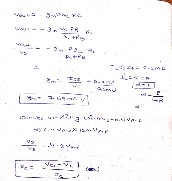
(a) Design the circuit (Find values for Rc, Rei and Rez) to amplify a 12mV sinusoidal...
 (a) Design the circuit (Find values for Rc, Rei and Rez) to amplify a 12mV sinusoidal signal from a microphone to a 0.4 V sinusoidal output signal, and make le = 0.2 mA. (20 points) (6) Draw complete small signal equivalent circuit of the amplifier. Clearly label all components. (Spoints) (c) Find values of input resistance (Rin), output resistance (Rout), and open circuit voltage gain ( Avo). (20 points) Assume B = 100, VBE.ON=0.7V, VA=00, and capacitors are very large...
QUESTION 7 Following circuit is the small-signal equivalent circuit of a common-emitter amplifier. Assume Ri 10...
 QUESTION 7 Following circuit is the small-signal equivalent circuit of a common-emitter amplifier. Assume Ri 10 kn, RB - 93 KO, RL - 8.5 kn. Small signal parameters are gm = 100 m, 5k and ro - 10 kn. Calculate the voltage gain Avvo/ Re & m} ube gmbe 3 ro " vo
ASSUME ALL CAPACITORS ARE INFINITE AND IDEAL. For a common-emitter amplifier with a voltage divider bias...
 ASSUME ALL CAPACITORS ARE INFINITE
AND IDEAL.
For a common-emitter amplifier with a voltage divider bias configuration using a single source, and given Rs = 2009, Rc = R = 2k2, VBE = 0.7V, Vcc= 20V and B = 100: a. Find R. and R for maximum symmetric output swing b. Determine Vopp (ideal and practical) c. Sketch the dc and ac load lines, showing the q-point and all intercept values of voltage and current.
ASSUME ALL CAPACITORS ARE INFINITE
AND IDEAL.
For a common-emitter amplifier with a voltage divider bias configuration using a single source, and given Rs = 2009, Rc = R = 2k2, VBE = 0.7V, Vcc= 20V and B = 100: a. Find R. and R for maximum symmetric output swing b. Determine Vopp (ideal and practical) c. Sketch the dc and ac load lines, showing the q-point and all intercept values of voltage and current.
A common-emitter BJT amplificr is shown in Fig.8.1. Note the DC biasing values and the BJTsmall-s...
 A common-emitter BJT amplificr is shown in Fig.8.1. Note the DC biasing values and the BJTsmall-signalmodel parameters from the class-signment #9 on DC Bia ing. Neglect the value of Rs in your calculations, k1 Rs-a k2: 1· Cal ulatethesmall-agalpannetas ofthe amplifi randcompletethecalculated valuesinTable8-1 Smalls-signal voltage gai, AVk Small-signal input resistance,k, Small-signaloutput resistance, Ro VW RC 2k C2 RB 570k Rs C1 1 10uP 0.1m 1 Vs CE RE 2k SINE(0 1mV 1kHz 0 0 00) tran 0 2ms 0 1us...
C- Amplifier: Consider figure 3. This circuit uses the JFET to amplify the input signal voltage F...
 C- Amplifier: Consider figure 3. This circuit uses the JFET to amplify the input signal voltage First the dc operation must be set. Use equation 1 and your previous data to calculate the value of Vas required to give I-0.5 mA. Determine the source resistance Rs needed to set this bias. Set up the circuit of figure 3 with your calculated value of Rs. Measure Vo and Vs to determine if your operating conditions are correct. Apply an input voltage...
QUESTION 1 Figure Q1 shows a common emitter (CE) and common Base (CB) cascade amplifier circuit....
 QUESTION 1 Figure Q1 shows a common emitter (CE) and common Base (CB) cascade amplifier circuit. Determine the input and output impedance, Z; and Zo, voltage gain, Avi and Av2 and total cascade voltage gain, Ayr and Ays. [25 marks) 2 +8V 1.5 kn 2.2 F 82 k2 3.3 k2 Vo 2.2 uf B = 100 6.8 k12 1 k 2 what B = 100 tuf ZA 5.6 k 2 47012 ZA V. 33 k2 IuF w 10k_2 -2V w...
Vsig = 10mV*sin(2Kπ) The circuit above is a common-emitter amplifier. Given the parameters in the circuit,...
 Vsig = 10mV*sin(2Kπ)
The circuit above is a common-emitter amplifier. Given the
parameters in the circuit,
1. If Rb1=10KΩ, Calculate Rb2, Ib, Ic, Ie, Re, transconductance
(gm), Current through Rb1 (I_rb1), and Current through Rb2(I_rb2),
Vb, Vc, Ve, Vce. Also, calculate Rc to achieve a voltage gain Av =
- 100 V/
(If Rb1 value does not match up, then choose your resistor
value for Rb1.)
2. If the amplitude of Vsig keeps increasing, at what amplitude
of the input...
Vsig = 10mV*sin(2Kπ)
The circuit above is a common-emitter amplifier. Given the
parameters in the circuit,
1. If Rb1=10KΩ, Calculate Rb2, Ib, Ic, Ie, Re, transconductance
(gm), Current through Rb1 (I_rb1), and Current through Rb2(I_rb2),
Vb, Vc, Ve, Vce. Also, calculate Rc to achieve a voltage gain Av =
- 100 V/
(If Rb1 value does not match up, then choose your resistor
value for Rb1.)
2. If the amplitude of Vsig keeps increasing, at what amplitude
of the input...
Please answer 2,3 and 4 VCC Rb Rs C1 Wwth VS Re Ce RL VO w...
 Please answer 2,3 and 4
VCC Rb Rs C1 Wwth VS Re Ce RL VO w + Figure 1 For the circuit of Figure 1 the following parameters are given with Vec = 15 volts DC: Rs = 0 ohm ra = 1000 ohm Rb = 1750 ohms CI = 10 microfarads gm = 30ms RL = 50 ohms Ce=0.3 microfarads Re = 145 ohms C2 may be considered very large vs is a sinusoidal voltage source of 1 volt...
Please answer 2,3 and 4
VCC Rb Rs C1 Wwth VS Re Ce RL VO w + Figure 1 For the circuit of Figure 1 the following parameters are given with Vec = 15 volts DC: Rs = 0 ohm ra = 1000 ohm Rb = 1750 ohms CI = 10 microfarads gm = 30ms RL = 50 ohms Ce=0.3 microfarads Re = 145 ohms C2 may be considered very large vs is a sinusoidal voltage source of 1 volt...
Please show steps. Draw the low-frequency small-signal model for a bipolar common-emitter amplifier. If VCC-11V and...
 Please show steps.
Draw the low-frequency small-signal model for a bipolar common-emitter amplifier. If VCC-11V and Rc-1ΜΩ what is the current necessary to achieve an output bias point of 10V? 1V? What are the small-signal values for gm and ro if VA-40V, the output bias point is 10V? 1V? What is the voltage gain, assuming that VA>> Vcc, at an output bias point of 10V? 1V? 1.
Please show steps.
Draw the low-frequency small-signal model for a bipolar common-emitter amplifier. If VCC-11V and Rc-1ΜΩ what is the current necessary to achieve an output bias point of 10V? 1V? What are the small-signal values for gm and ro if VA-40V, the output bias point is 10V? 1V? What is the voltage gain, assuming that VA>> Vcc, at an output bias point of 10V? 1V? 1.
 [1] The circuit diagram on the left below is a common emitter amplifier. It is the full complement of components for this type of amplifier ready for AC analysis. This amplifier will be discussed in lecture prior to the lab exercises. However, with the circuit including only Rc. RE, Ri, and R2 as shown in the figure on the right, proceed with the design for a DC operating point of the common emitter amplifier. The following parameters are given: Vcc...
 (a) Design the circuit (Find values for Rc, Rei and Rez) to amplify a 12mV sinusoidal signal from a microphone to a 0.4 V sinusoidal output signal, and make le = 0.2 mA. (20 points) (6) Draw complete small signal equivalent circuit of the amplifier. Clearly label all components. (Spoints) (c) Find values of input resistance (Rin), output resistance (Rout), and open circuit voltage gain ( Avo). (20 points) Assume B = 100, VBE.ON=0.7V, VA=00, and capacitors are very large...
 QUESTION 7 Following circuit is the small-signal equivalent circuit of a common-emitter amplifier. Assume Ri 10 kn, RB - 93 KO, RL - 8.5 kn. Small signal parameters are gm = 100 m, 5k and ro - 10 kn. Calculate the voltage gain Avvo/ Re & m} ube gmbe 3 ro " vo
 ASSUME ALL CAPACITORS ARE INFINITE
AND IDEAL.
For a common-emitter amplifier with a voltage divider bias configuration using a single source, and given Rs = 2009, Rc = R = 2k2, VBE = 0.7V, Vcc= 20V and B = 100: a. Find R. and R for maximum symmetric output swing b. Determine Vopp (ideal and practical) c. Sketch the dc and ac load lines, showing the q-point and all intercept values of voltage and current.
ASSUME ALL CAPACITORS ARE INFINITE
AND IDEAL.
For a common-emitter amplifier with a voltage divider bias configuration using a single source, and given Rs = 2009, Rc = R = 2k2, VBE = 0.7V, Vcc= 20V and B = 100: a. Find R. and R for maximum symmetric output swing b. Determine Vopp (ideal and practical) c. Sketch the dc and ac load lines, showing the q-point and all intercept values of voltage and current.
 A common-emitter BJT amplificr is shown in Fig.8.1. Note the DC biasing values and the BJTsmall-signalmodel parameters from the class-signment #9 on DC Bia ing. Neglect the value of Rs in your calculations, k1 Rs-a k2: 1· Cal ulatethesmall-agalpannetas ofthe amplifi randcompletethecalculated valuesinTable8-1 Smalls-signal voltage gai, AVk Small-signal input resistance,k, Small-signaloutput resistance, Ro VW RC 2k C2 RB 570k Rs C1 1 10uP 0.1m 1 Vs CE RE 2k SINE(0 1mV 1kHz 0 0 00) tran 0 2ms 0 1us...
 C- Amplifier: Consider figure 3. This circuit uses the JFET to amplify the input signal voltage First the dc operation must be set. Use equation 1 and your previous data to calculate the value of Vas required to give I-0.5 mA. Determine the source resistance Rs needed to set this bias. Set up the circuit of figure 3 with your calculated value of Rs. Measure Vo and Vs to determine if your operating conditions are correct. Apply an input voltage...
 QUESTION 1 Figure Q1 shows a common emitter (CE) and common Base (CB) cascade amplifier circuit. Determine the input and output impedance, Z; and Zo, voltage gain, Avi and Av2 and total cascade voltage gain, Ayr and Ays. [25 marks) 2 +8V 1.5 kn 2.2 F 82 k2 3.3 k2 Vo 2.2 uf B = 100 6.8 k12 1 k 2 what B = 100 tuf ZA 5.6 k 2 47012 ZA V. 33 k2 IuF w 10k_2 -2V w...
 Vsig = 10mV*sin(2Kπ)
The circuit above is a common-emitter amplifier. Given the
parameters in the circuit,
1. If Rb1=10KΩ, Calculate Rb2, Ib, Ic, Ie, Re, transconductance
(gm), Current through Rb1 (I_rb1), and Current through Rb2(I_rb2),
Vb, Vc, Ve, Vce. Also, calculate Rc to achieve a voltage gain Av =
- 100 V/
(If Rb1 value does not match up, then choose your resistor
value for Rb1.)
2. If the amplitude of Vsig keeps increasing, at what amplitude
of the input...
Vsig = 10mV*sin(2Kπ)
The circuit above is a common-emitter amplifier. Given the
parameters in the circuit,
1. If Rb1=10KΩ, Calculate Rb2, Ib, Ic, Ie, Re, transconductance
(gm), Current through Rb1 (I_rb1), and Current through Rb2(I_rb2),
Vb, Vc, Ve, Vce. Also, calculate Rc to achieve a voltage gain Av =
- 100 V/
(If Rb1 value does not match up, then choose your resistor
value for Rb1.)
2. If the amplitude of Vsig keeps increasing, at what amplitude
of the input...
 Please answer 2,3 and 4
VCC Rb Rs C1 Wwth VS Re Ce RL VO w + Figure 1 For the circuit of Figure 1 the following parameters are given with Vec = 15 volts DC: Rs = 0 ohm ra = 1000 ohm Rb = 1750 ohms CI = 10 microfarads gm = 30ms RL = 50 ohms Ce=0.3 microfarads Re = 145 ohms C2 may be considered very large vs is a sinusoidal voltage source of 1 volt...
Please answer 2,3 and 4
VCC Rb Rs C1 Wwth VS Re Ce RL VO w + Figure 1 For the circuit of Figure 1 the following parameters are given with Vec = 15 volts DC: Rs = 0 ohm ra = 1000 ohm Rb = 1750 ohms CI = 10 microfarads gm = 30ms RL = 50 ohms Ce=0.3 microfarads Re = 145 ohms C2 may be considered very large vs is a sinusoidal voltage source of 1 volt...
 Please show steps.
Draw the low-frequency small-signal model for a bipolar common-emitter amplifier. If VCC-11V and Rc-1ΜΩ what is the current necessary to achieve an output bias point of 10V? 1V? What are the small-signal values for gm and ro if VA-40V, the output bias point is 10V? 1V? What is the voltage gain, assuming that VA>> Vcc, at an output bias point of 10V? 1V? 1.
Please show steps.
Draw the low-frequency small-signal model for a bipolar common-emitter amplifier. If VCC-11V and Rc-1ΜΩ what is the current necessary to achieve an output bias point of 10V? 1V? What are the small-signal values for gm and ro if VA-40V, the output bias point is 10V? 1V? What is the voltage gain, assuming that VA>> Vcc, at an output bias point of 10V? 1V? 1.
Most questions answered within 3 hours.
-
(CO 2) A field can be added to a report to
values for two or more...
asked 14 minutes ago -
Identify 3 research scenarios that might provide a low,
medium, and high degree of variability in...
asked 37 minutes ago -
how
does gravity affect the trajectory of projectile? what would be the
shape of the trajactory...
asked 1 hour ago -
Two small plastic spheres are given positive electrical charges.
When they are a distance of 15.4...
asked 1 hour ago -
An acidic solution containing gold ions is
electrolyzed, producing gaseous oxygen (from water) at the anode...
asked 1 hour ago -
Assume that the population of Mexico is 128
million and that the population increases 1.01
percentannually....
asked 2 hours ago -
Can someone please help me add appropriate descriptive
comments to each line of code in the...
asked 2 hours ago -
Romeo wishes to throw a bouquet of flowers to Juliet, who is on
a second-story balcony,...
asked 3 hours ago -
Why is QE a controversial monetary policy tool.
A. It may lead to excessive inflation.B. By...
asked 4 hours ago -
Principles of Programming midterm study guide help!
1.)
______ Which of the following would reference the...
asked 3 hours ago -
A finite potential well has depth U0 = 2.78 eV . What is the
penetration distance...
asked 4 hours ago -
1. The bus bars of a power station are in two sections A and B
separated...
asked 4 hours ago